RC522 RFID In-Depth Guide: Understanding How It Works & Uses It with Arduino
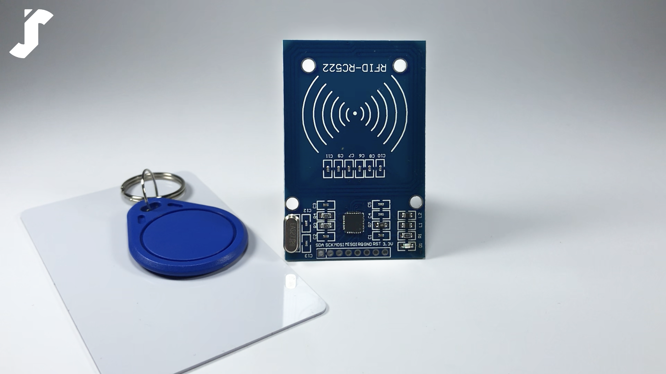
The RC522 RFID (radio frequency identification) is a wireless product that includes a radio frequency reader, card, and keychain. The parts communicate and exchange data through an electromagnetic field with the help of the coiled copper on the reader’s PCB (printed circuit board) and the coils within the card and keychain.
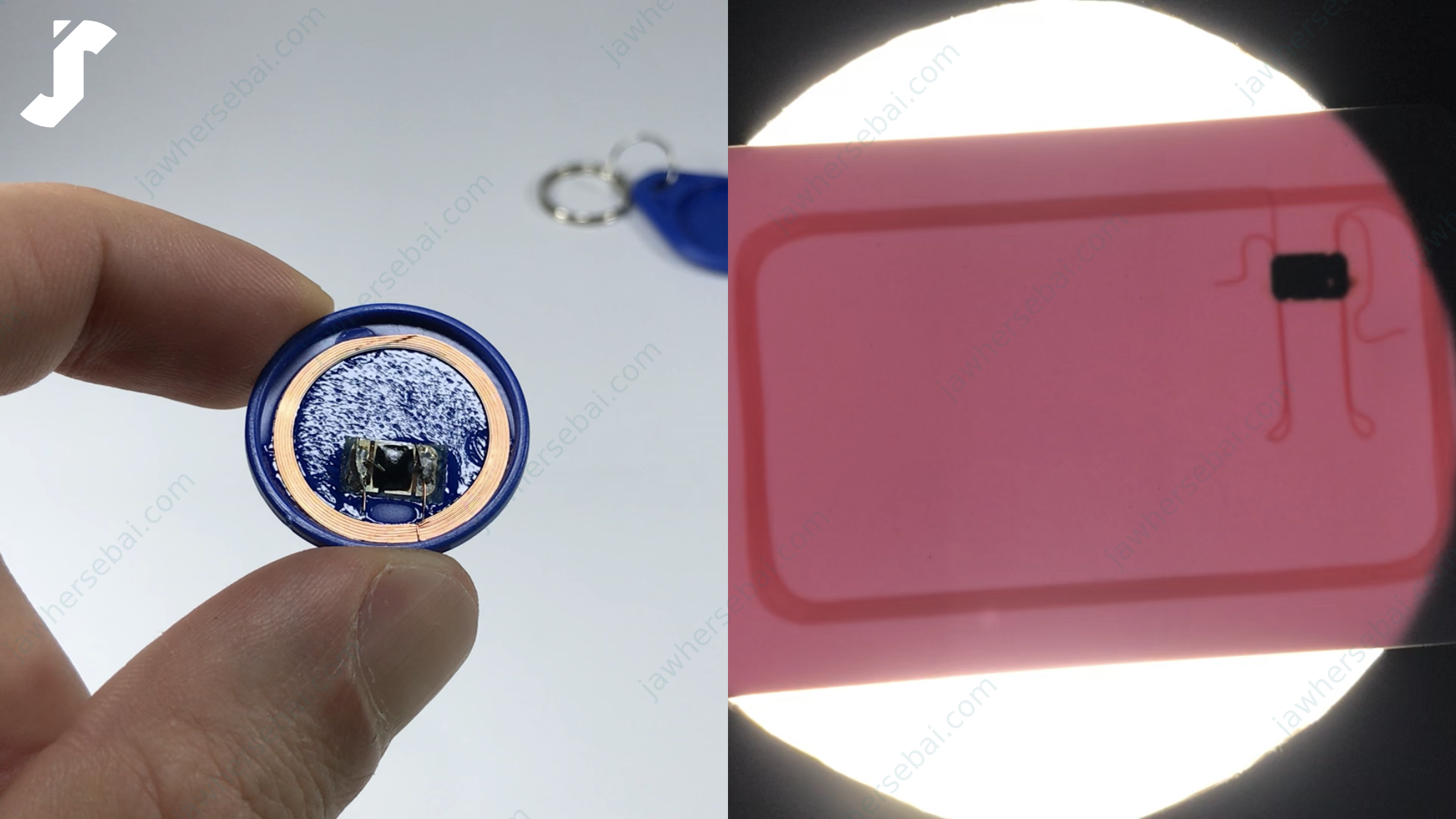
How It Works
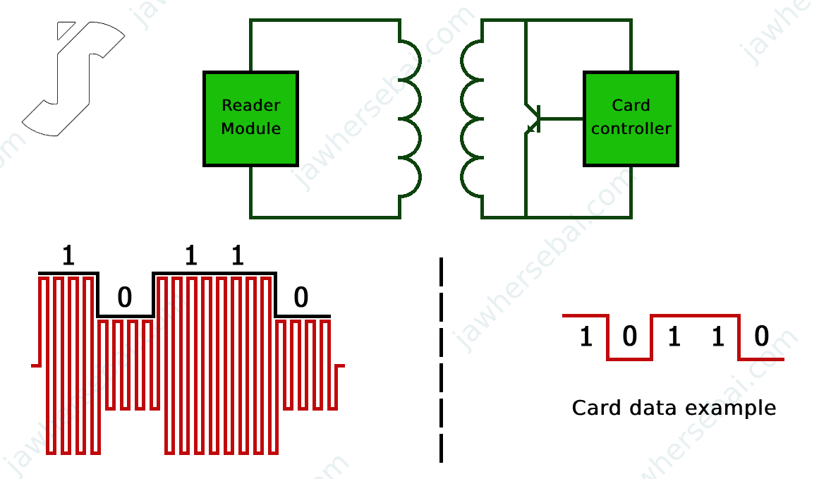
When the reader is in operation, it will generate a variable electromagnetic field around its coil, which powers the nearby card or keychain according to Faraday’s law of induction. The card or the keychain then exchanges data with the reader through a technique called load manipulation.
Load Manipulation
When the integrated circuit in the card or keychain is on power, a built-in transistor shortens the coil by switching ON and OFF in sequence according to the stored data, leading to an increase in the current consumption from the reader’s coil. The reader then measures the change in power consumption and converts it to ones and zeros.
Pinout
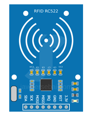
- 3.3V is the power supply pin.
- RST is the reset pin, and it also has a role in switching off the module.
- GND is the ground pin.
- IRQ is the interrupt pin, and it gives an alert that there is a card or keychain nearby.
- The MISO (Master In Slave Out) pin plays three roles: MISO for the SPI connection, SCL for the I2C connection, and TX for the UART connection.
- The MOSI (Master Out Slave In) pin is the SPI input to the module.
- The SCK pin is the serial clock pin.
- The SDA pin plays three roles: SDA when using the I2C connection, SS when using the SPI connection, and RX for the UART connection.
Connecting the RC522 RFID to Arduino
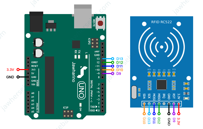
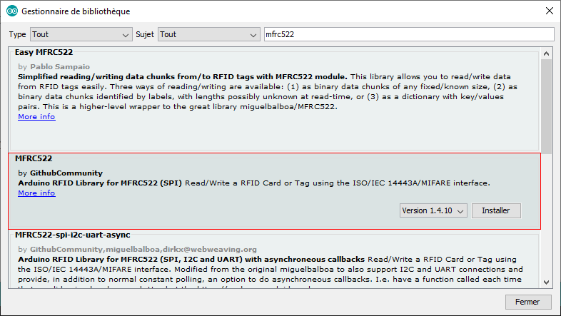
Since I started learning to program Arduino, the availability of libraries has made it easier for me to control the most commonly used sensors, displays, and modules. As long as the MFRC522 library is available in the GitHub community, you can download it by navigating to Sketch > Include Library > Manage Libraries and searching MFRC522.
After downloading the RFID library, I would like to get my card and keychain UID for future projects. I went to File > Examples > MFRC522 > DumpInfo and uploaded the sketch. By opening the serial monitor, I can see the card UID, SAK, type, size, and model of the memory.

- The UID is unique for each card or keychain.
- The SAK is the manufacturer identifier.
- The card is a MIFARE type with a storage capacity of 1 KB.
- The model is composed of 16 sectors, each sector is divided into 4 blocks, and each block can store 16 bytes of data. The 4th block of each sector is called Sector Trailer, it contains two security keys called Key A and Key B, with a 4-bit segment known as the Access Bit situated between them. Without knowledge of at least one of the two keys, it is impossible to access or modify the memory data.
RFID Card Reader Project: Indicating Correct and Incorrect Cards
In this project, tapping the correct card on the reader will turn on a green LED for one second, whereas presenting an incorrect card will cause a red LED to illuminate for one second.
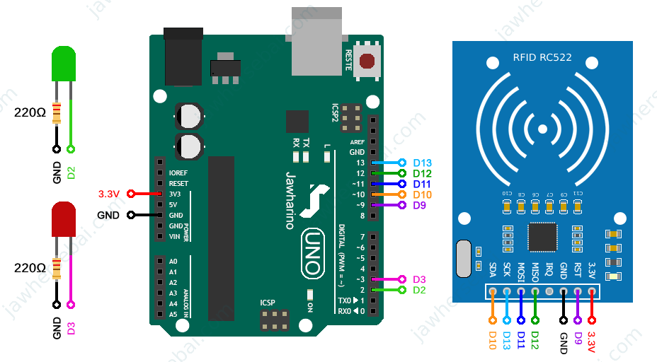
Arduino Sketch
#include <SPI.h>
#include <MFRC522.h>
#define RST_PIN 9
#define SS_PIN 10
#define ledGreen 2
#define ledRed 3
MFRC522 mfrc522(SS_PIN, RST_PIN);
byte tagUID[4] = {0xD5, 0xE6, 0xB0, 0xAC};
void setup()
{
  Serial.begin(9600);
  SPI.begin();
  mfrc522.PCD_Init();
  pinMode(ledRed, OUTPUT);
  pinMode(ledGreen, OUTPUT);
}
void loop()
{
  if ( ! mfrc522.PICC_IsNewCardPresent()) {
  return false;
  }
  if ( ! mfrc522.PICC_ReadCardSerial()) {
  return false;
  }
  if (mfrc522.uid.uidByte[0] == tagUID[0] &&
      mfrc522.uid.uidByte[1] == tagUID[1] &&
      mfrc522.uid.uidByte[2] == tagUID[2] &&
      mfrc522.uid.uidByte[3] == tagUID[3] )
      {
        digitalWrite(ledGreen, HIGH);
        digitalWrite(ledRed, LOW);
        delay(1000);
      }
      else
      {
        digitalWrite(ledGreen, LOW);
        digitalWrite(ledRed, HIGH);
        delay(1000);
      }
  mfrc522.PICC_HaltA();
  digitalWrite(ledGreen, LOW);
  digitalWrite(ledRed, LOW);
} 