KY-37 Sound Sensor: How to Detect Sound & Turn the Light with Two Claps

In this tutorial I will share with you how the KY-37 sound sensor works and how to use it with an Arduino board to turn on an LED with two claps.
Sensor Pinout
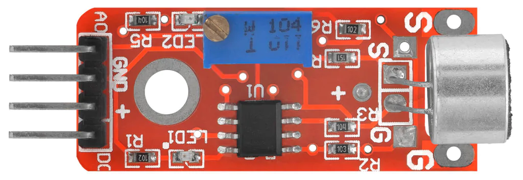
- The AO pin is the analog output, and it will output a sinusoidal signal corresponding to the detected sound.
- The GND and the “+” are for powering up the sensor with 5V.
- The DO pin is the digital output, and it will output HIGH or LOW voltage corresponding to the detected sound and according to the potentiometer position.
The KY-37 sound sensor potentiometer is for adjusting the sensitivity of the microphone by setting a threshold to trigger the DO pin. Rotating the potentiometer to the right increases the sensitivity and to the left decreases it.
How Does the KY-37 Sensor Detect the Sound
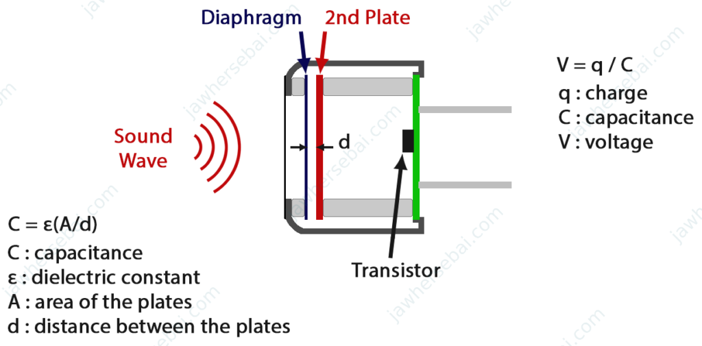
The KY-37 sound sensor mainly uses an electret microphone to detect sound vibrations and convert them into electrical energy. This microphone uses a special capacitor but does not function like a normal one. Therefore, to have a better understanding of how the sensor works, you need basic knowledge of capacitors, including their definition, operation, and composition.

The sound sensor capacitor is manufactured in such a way that one of its metal plates is coated with an electret material, which keeps the capacitor permanently charged for years.
The second plate is a membrane that is sensitive to sound vibrations. When the membrane moves according to the pressure of the sound waves, the distance between itself and the other plate will change. As a result, the capacitance of the capacitor changes, and thus the electrical voltage changes.
Controlling an LED with Two Claps Using KY-37 Sensor and Arduino
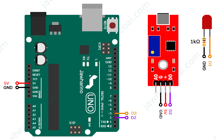
In this project, we will use the KY-37 sound sensor with an Arduino board to turn on an LED with two claps. Through Arduino programming, we’ll count the number of claps detected and measure the time between them using the millis function. When two successive claps are within the set duration, the LED will light up. Follow the wiring connections as shown below, and use the provided Arduino sketch to program your board.

Arduino Sketch
int sensorPin = 2;
int sensorState;
int ledPin = 3;
int ledState = 0;
int clap = 0;
long first_clap_time = 0;
long last_clap_time = 0;
void setup() {
  pinMode(sensorPin, INPUT);
  pinMode(ledPin, OUTPUT);
}
void loop() {
sensorState = digitalRead(sensorPin);
if (sensorState == 1)
{
  if (clap == 0)
  {
    clap++;
    first_clap_time = last_clap_time = millis();
  }
  else if (clap > 0 && millis()-last_clap_time >= 50)
  {
    clap++;
    last_clap_time = millis();
  }
}
if (millis()-first_clap_time >= 500)
{
  if (clap == 2)
  {
    if (ledState == 0)
    {
      ledState = 1;
      digitalWrite(ledPin, HIGH);
    }
    else if (ledState == 1)
    {
      ledState = 0;
      digitalWrite(ledPin, LOW);
    }
  }
clap = 0;
}
}
Sources
- Electret microphone: Wikipedia
