HC-SR501 PIR Sensor: Understanding Operation & Motion Detection
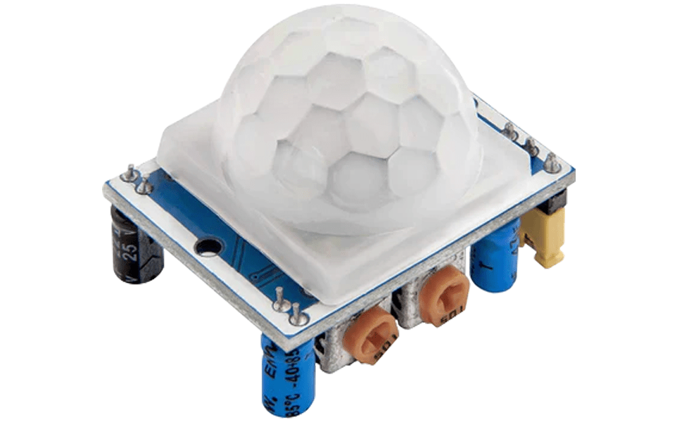
Every object with a temperature above -273.15 degrees Celsius emits heat as infrared radiation, which is invisible to the human eye due to its longer wavelengths, ranging from 700 nanometers to 1,000,000 nanometers. The HC-SR501 PIR sensor is capable of detecting a portion of this infrared radiation within the range of 7,000 to 14,000 nanometers.

Getting Familiar with the HC-SR501 PIR Sensor
The HC-SR501 PIR sensor consists of a pyroelectric sensor that contains two pyroelectric material elements within its metal casing and a specialized lens known as a Fresnel lens to focus the infrared radiation onto the pyroelectric sensor.
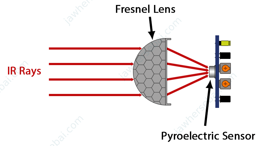
Pyroelectric Material
Pyroelectric materials produce a voltage when heated or cooled due to their natural polarization. In my experiment, bringing a heat source close to such a material causes the voltage to increase. Conversely, removing the heat source reverses the material’s polarity, causing the voltage to eventually return to zero.
PIR Sensor Design
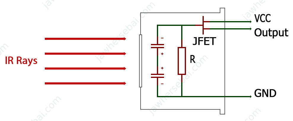
The PIR sensor has two pyroelectric elements connected in series, with their respective poles facing each other (either positive or negative). This design, utilizing dual pyroelectric elements, aims to detect changes in infrared levels to initiate an action while minimizing false alarms. Additionally, since this element possesses piezoelectric properties, meaning that it is capable of generating voltage under mechanical stress, the sensor is equipped with two pyroelectric elements to cancel each other in the presence of nearby vibrations.
How It Works
Example
When two batteries with the same voltage are connected in series with their positive poles facing each other, measuring the voltage across their terminals with a voltmeter will result in 0V. If one battery has a higher or lower voltage than the other, the total voltage measured will be the difference between their voltages, which could be a positive or negative value, depending on which battery has the higher voltage.

This previous example describes what goes on inside the pyroelectric sensor. When there’s no movement in front of the sensor, both pyroelectric elements detect equal amounts of IR radiation from the environment, leading to no voltage difference. However, when a warm body moves in front of the sensor, it alters the IR radiation levels. One of the pyroelectric materials senses this change before the other, within microseconds, resulting in a measurable voltage difference.
Hardware Overview
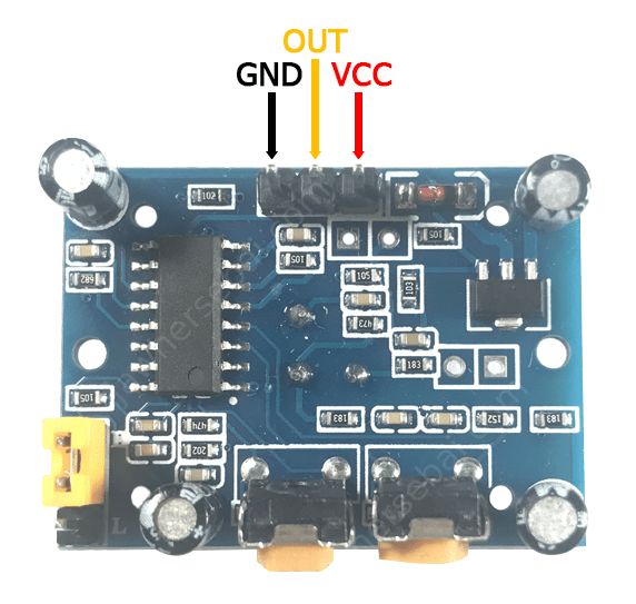
- VCC and GND pins are for powering up the sensor with a voltage between 5V and 12V, while the maximum current draw is less than 2 mA.
- The OUT pin outputs 3.3V when there is motion within the sensor field of detection and 0V when there is no motion.
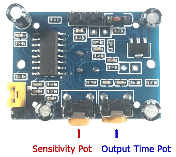
- The Output Time Pot is for controlling the time that the OUT-pin stays HIGH. Rotating this potentiometer to the very left keeps the OUT pin at a HIGH level for 3 seconds, while turning it to the very right keeps the OUT pin at a HIGH level for 5 minutes.
- The Sensitivity Pot adjusts the sensor’s range, covering distances from 3 to 7 meters.
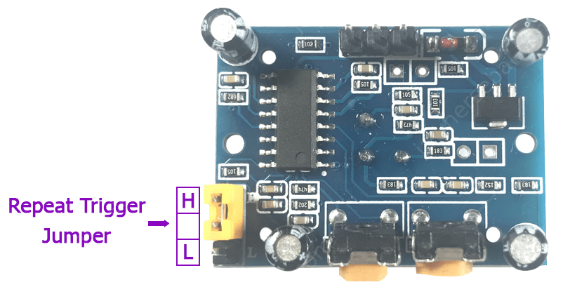
The Repeat Trigger Jumper features three pins. Connecting the middle pin to the L pin allows the sensor to operate normally by keeping the OUT pin at a HIGH level for the duration set by the output time potentiometer whenever there is movement. Conversely, linking the middle pin to the H pin causes the sensor to disregard the Output Time Potentiometer’s setting, maintaining the OUT pin at a HIGH level if there is ongoing movement in front of the sensor.
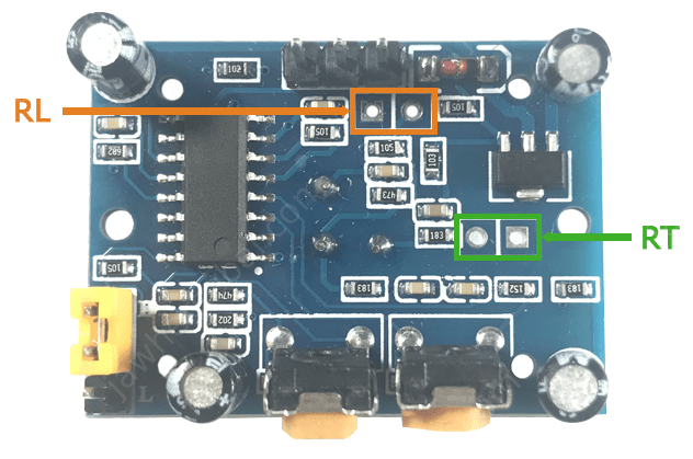
- RT: These holes are for connecting a thermistor that allows the PIR sensor to work perfectly at a high temperature.
- RL: These holes are for connecting a Light Dependent Resistor (LDR), which allows the PIR sensor to work only in the dark.
Detecting Motion with the HC-SR501 PIR Sensor
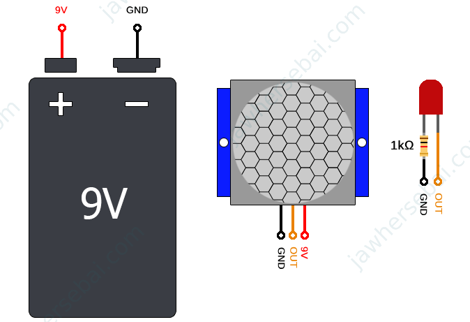
The advantage of the HC-SR501 PIR Sensor is that you can use it without any microcontroller. Simply supply it with a voltage between 5V and 12V and utilize the OUT pin to turn on an LED, for example.
Using an Arduino Board
To integrate the PIR sensor with an Arduino board, you can set it up to turn on an LED and display on an LCD “Motion Detected” when there is movement in front of the sensor, and display “No Motion” in the absence of movement.
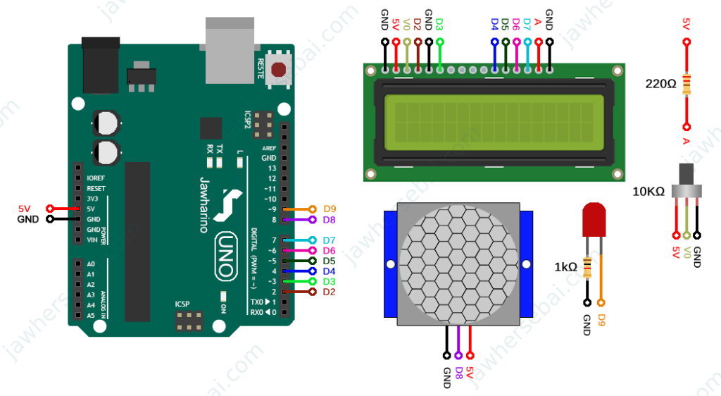
Arduino Sketch
#include <LiquidCrystal.h>
const int rs = 2, en = 3, d4 = 4, d5 = 5, d6 = 6, d7 = 7;
LiquidCrystal lcd(rs, en, d4, d5, d6, d7);

int ledPin = 9;
int pirPin = 8;
int pirValue;

void setup() {
  Serial.begin(9600);
  lcd.begin(16, 2);
  pinMode(ledPin, OUTPUT);
  pinMode(pirPin, INPUT);
}

void loop() {
    pirValue = digitalRead(pirPin);
    Serial.println(pirValue);
    delay(2000);
    if (pirValue == 1){
      digitalWrite(ledPin, HIGH);
      lcd.setCursor(0, 0);
      lcd.print("Motion detected");
      delay(100);
      lcd.clear();
    }
    else{
      digitalWrite(ledPin, LOW);
      lcd.setCursor(0, 0);
      lcd.print("No Motion");
      delay(100);
      lcd.clear();
    }
}
If you don’t know how to use the 1602 LCD with an Arduino board, check out my tutorial on How LCD Works And How to Use It with Arduino.
Sources
- HC-SR501 PIR Sensor Datasheet: mpja.com
