1602 LCD: Operation Phenomenon & Integration with Arduino

How LCD works
Light Polarization
LCD screens operate using the phenomenon of light polarization, allowing them to function efficiently with minimal energy consumption. The light around us vibrates in multiple directions, which is known as unpolarized light. To transform unpolarized light into polarized light, we need a polarizing filter, which permits only the vibrations of light in a single plane to pass through.
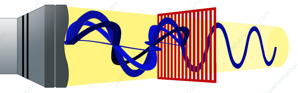
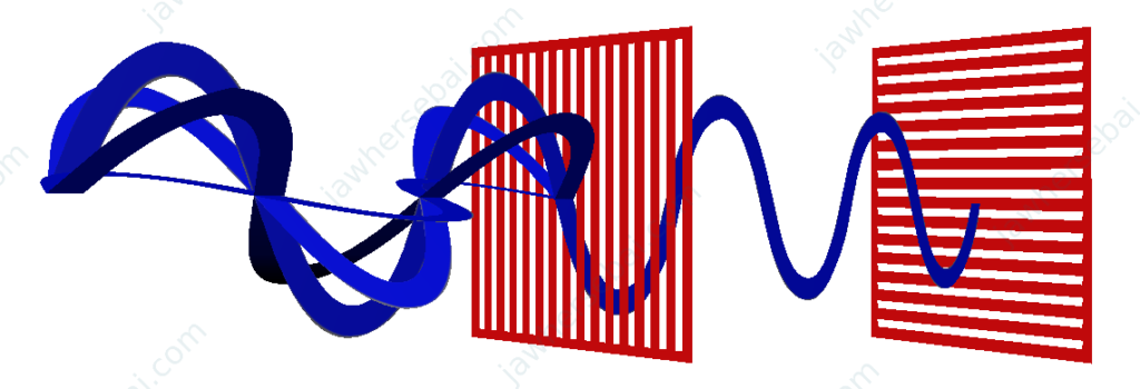
When two polarizing filters are perpendicular to each other, light that passes through the first filter cannot pass through the subsequent filter, creating a dark visual effect.
The 1602 LCD Composition
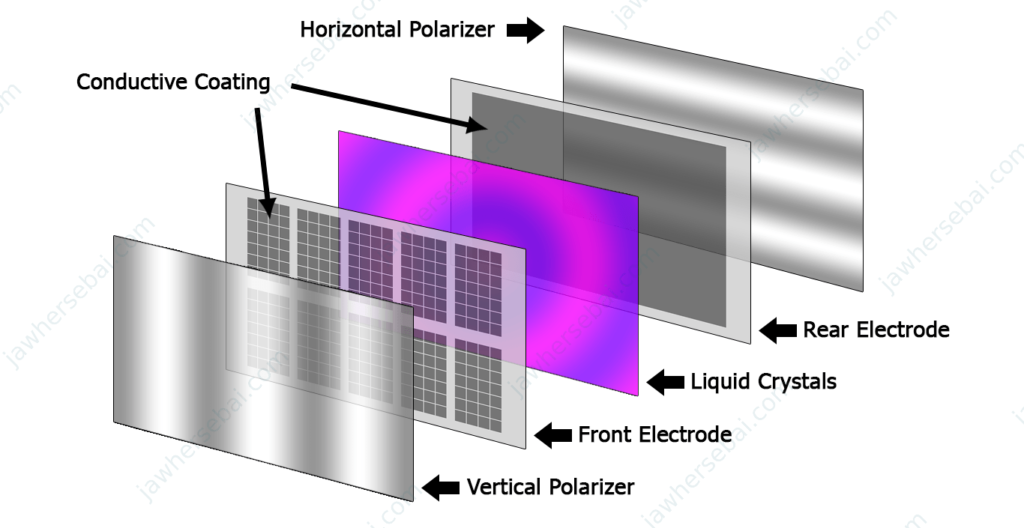
The 1602 LCD screen consists of two polarizing filters, with the rear and front electrodes coated in a conductive layer. The front electrode is shaped to match the specific display needed, which varies from one LCD to another depending on the application’s requirements. In the middle are the liquid crystals, a material with molecules that uniquely rotate the light’s polarization, allowing it to pass through the subsequent polarizer.
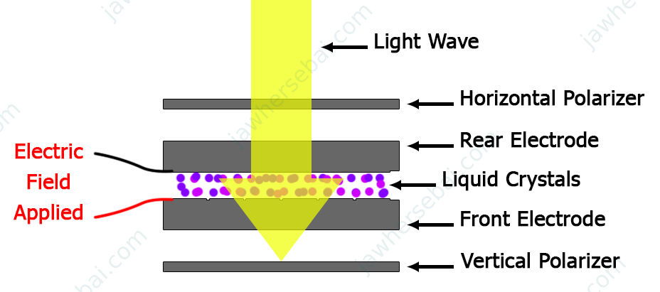
When we apply a voltage to a liquid crystal material, it loses the ability to rotate light’s polarization. Consequently, darkness appears in the area exposed to the electric field, as the light cannot pass through the subsequent polarizer.
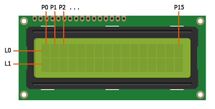
Getting Familiar with the 1602 LCD Pinout
LCD stands for Liquid Crystal Display, and 1602 means it has 16 columns and 2 rows. On the screen, there are 32 matrices (16×2), each composed of 40 pixels (5*8) to display a character.
Because this is CMOS technology, VSS is the GND pin and VDD is the VCC pin.
- V0 is the brightness control voltage of the LCD characters.
- RS is the Register Select pin.
For example, to show a message on the LCD, the RS pin should be set to HIGH. Conversely, to issue commands to the LCD, such as clearing the message, the RS pin should be set to LOW.
- RW is the Read or Write pin.
If Rw = HIGH, we can read data from the HD44780 registers. And if Rw = LOW, we can write data to the HD44780 registers.
- E is the Enable pin.
Setting the E pin to HIGH ensures visibility on the LCD screen. And if not, nothing will be displayed.
- From D0 to D7 are the 8 DATA Input pins.
- A is the anode of the backlight LED.
- K is the cathode of the backlight LED.
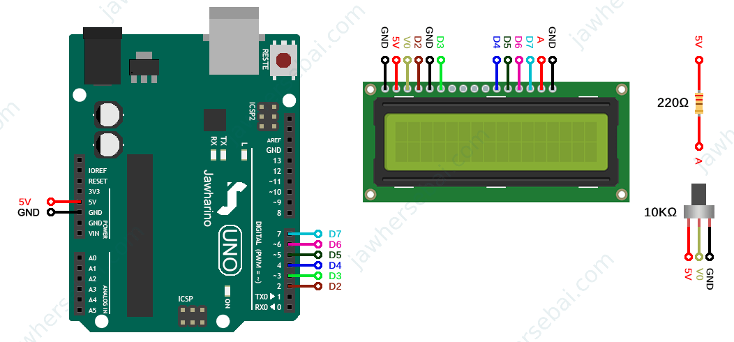
Connecting the 1602 LCD to an Arduino Board
Connecting a 1602 LCD to an Arduino UNO board can use up many of the digital input/output pins due to the display’s numerous pins. Fortunately, the LCD can operate in a mode that reduces the number of data input pins needed from eight to four.
4-Bit Mode
For instance, to display the letter ‘H’ on the LCD, you would input the binary sequence 0100 1000 into the 8 data pins according to the ASCII table, utilizing 8 digital I/O pins on the Arduino board. In 4-bit mode, you can divide the 8-bit binary number into two 4-bit nibbles. You would first input the higher nibble 1000 into the upper data pins D4, D5, D6, and D7, and then the lower nibble 0100.
The liquid crystal library helps a lot in writing the sketch. It comes with the Arduino IDE software, so you don’t have to install it. To display your first message, go to File > Examples > LiquidCrystal > HelloWorld, or use the following example.
#include <LiquidCrystal.h>// include liquidcrystal library
LiquidCrystal lcd(2, 3, 4, 5, 6, 7);// create LCD object with the following parameters (RS=2, E=3, D4=4, D5=5, D6=6, D7=7)
void setup() {
  lcd.begin(16, 2);// set the type of LCD you are using, 16 columns and 2 rows
  lcd.print("Hello world!");// Print "Hello world!" to the LCD
  lcd.setCursor(0,1);// set the cursor to column 0, line 2
  lcd.print("stay home y'all!");// Print "stay home y'all!" to the LCD
}
void loop() {
  // as long as we are printing these messages once, we write them all in void setup, the place where the code will run once
}
So basically, to display any word, we need to writelcd.print("Hello world!");
And to select the desired location for displaying our message, we position the cursor at the target spot and then enter our messagelcd.setCursor(0,1);//note that 0 is the 1st column and 1 is the second rowlcd.print("stay home y'all!");
Try exploring the example sketches included with the library to enhance your understanding of the LCD’s capabilities, like the blinking or scrolling effects that draw the user’s attention.
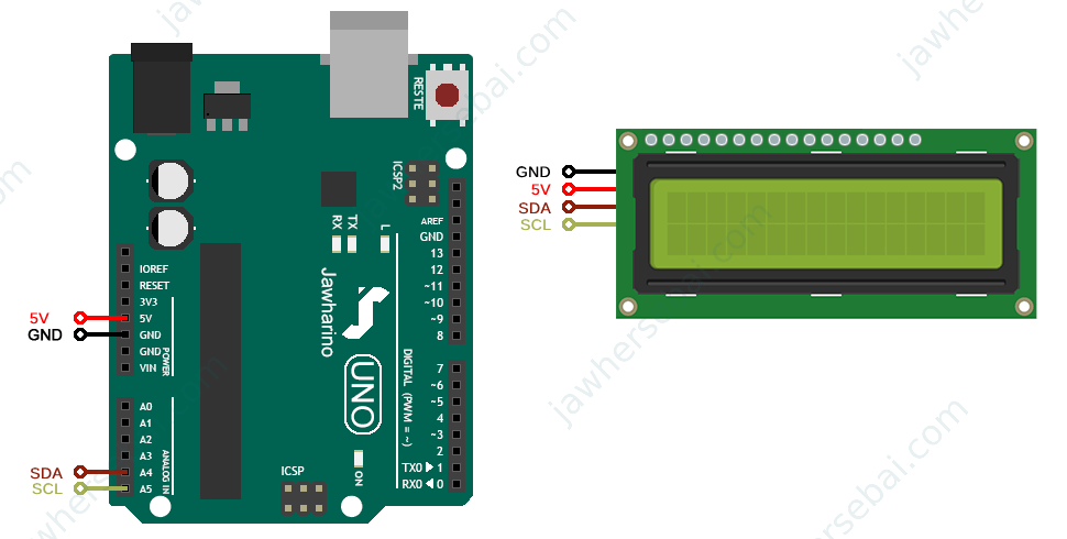
Using I2C Adapter
With the I2C serial interface adapter, we can use the I2C protocol to transmit serial data through the SDA and SCL pins on the Arduino board, which correspond to the A4 and A5 analog pins, respectively. And that saves us all the digital I/O pins.
First of all, it is essential to determine the I2C Interface adapter address to execute the main sketch.
Once you have everything hooked up as illustrated above, go to File > Examples > Wire > i2c_scanner, or just copy and paste the following sketch on your Arduino IDE. After uploading, open the serial monitor and copy your address (for example, “0x27”).
// --------------------------------------
// i2c_scanner
//
// Version 1
// This program (or code that looks like it)
// can be found in many places.
// For example on the Arduino.cc forum.
// The original author is not know.
// Version 2, Juni 2012, Using Arduino 1.0.1
// Adapted to be as simple as possible by Arduino.cc user Krodal
// Version 3, Feb 26 2013
// V3 by louarnold
// Version 4, March 3, 2013, Using Arduino 1.0.3
// by Arduino.cc user Krodal.
// Changes by louarnold removed.
// Scanning addresses changed from 0...127 to 1...119,
// according to the i2c scanner by Nick Gammon
// https://www.gammon.com.au/forum/?id=10896
// Version 5, March 28, 2013
// As version 4, but address scans now to 127.
// A sensor seems to use address 120.
// Version 6, November 27, 2015.
// Added waiting for the Leonardo serial communication.
//
//
// This sketch tests the standard 7-bit addresses
// Devices with higher bit address might not be seen properly.
//
#include <Wire.h>
void setup() {
  Wire.begin();
  Serial.begin(9600);
  while (!Serial); // Leonardo: wait for serial monitor
  Serial.println("\nI2C Scanner");
}
void loop() {
  int nDevices = 0;
  Serial.println("Scanning...");
  for (byte address = 1; address < 127; ++address) {
    // The i2c_scanner uses the return value of
    // the Write.endTransmisstion to see if
    // a device did acknowledge to the address.
    Wire.beginTransmission(address);
    byte error = Wire.endTransmission();
    if (error == 0) {
      Serial.print("I2C device found at address 0x");
      if (address < 16) {
        Serial.print("0");
      }
      Serial.print(address, HEX);
      Serial.println("  !");
      ++nDevices;
    } else if (error == 4) {
      Serial.print("Unknown error at address 0x");
      if (address < 16) {
        Serial.print("0");
      }
      Serial.println(address, HEX);
    }
  }
  if (nDevices == 0) {
    Serial.println("No I2C devices found\n");
  } else {
    Serial.println("done\n");
  }
  delay(5000); // Wait 5 seconds for next scan
}
After obtaining the address, go to Sketch > Include Library > Manage Libraries, and search for liquid crystal and install the one by Frank De Brabander.
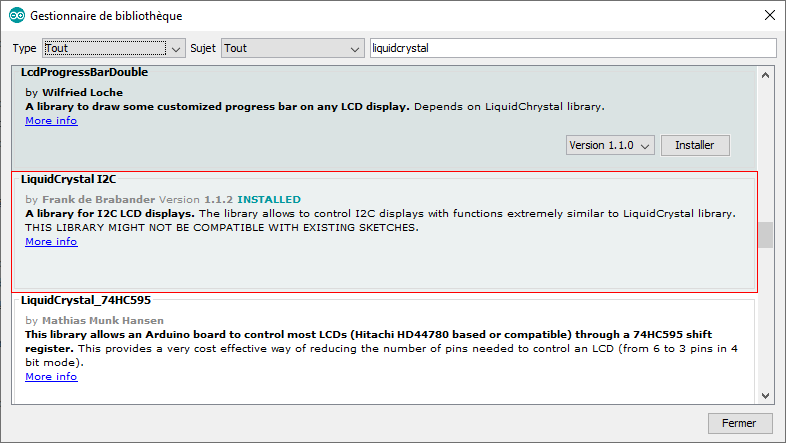
Now upload the sketch by going to File > Examples > LiquidCrystal I2C > HelloWorld, or copy the following sketch, and do not forget to change the address of your I2C adapter.
#include <Wire.h> // include wire library
#include <LiquidCrystal_I2C.h> // include liquidcrystal i2c library
LiquidCrystal_I2C lcd(0x27,16,2);// create lcd object with the following parameters (0x27=address, 16=16 columns, 2=2 rows)
void setup()
{
  lcd.init();// initialize the lcd
  lcd.backlight();// backlight is on
  lcd.setCursor(0,0);// set the cursor to column 0, line 1
  lcd.print("Hello world!");// Print "Hello world!" to the LCD
  lcd.setCursor(0,1);// set the cursor to column 0, line 2
  lcd.print("stay home y'all!");// Print "stay home y'all!" to the LCD
}
void loop()
{
  // as long as we are printing these messages once, we write them all in void setup, the place where the code will run once
}
Sources
- Polarization of light: quora.com
- Liquid-crystal display: Wikipedia
- 16×2 LCD Display Module: circuitdigest.com
- LCD 4bit and 8bit mode – Major difference: engineersgarage.com