How Does The RC522 RFID Works And How To Use It With Arduino
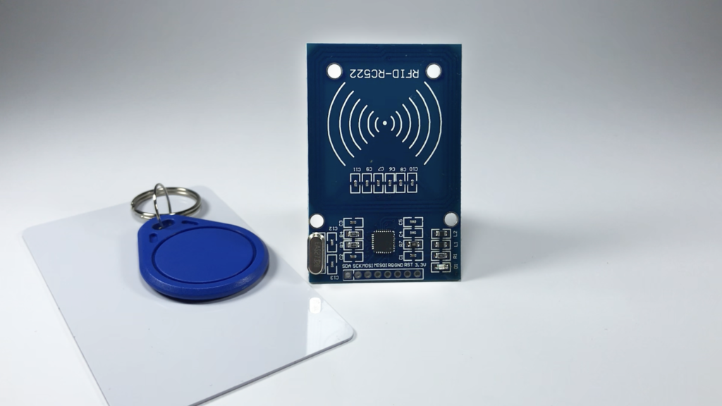
RFID or Radio Frequency Identification is a wireless technology consisting mostly of a radio frequency reader and a radio frequency card, they work and they exchange data together using electromagnetic waves.
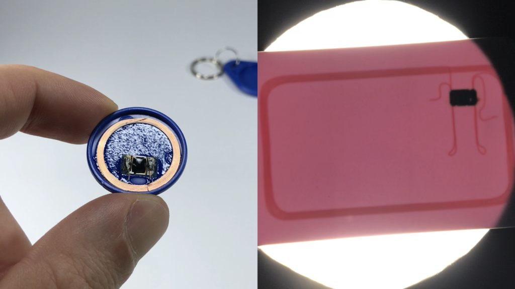
On the PCB of the RC522 RFID reader, there is a coil placed there to generate an electromagnetic field when the module applies a sinusoidal current to its poles. on the other hand, the RFID card also has a little integrated circuit and a coil inside of it to receive electricity wirelessly.
The RC522 RFID Pin Out
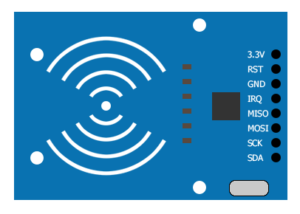
- 3.3V is the power supply pin, connecting this pin to 5V might destroy the module.
- RST is the reset pin it has a role also to switch off the module.
- GND is the ground pin.
- IRQ is the interrupt pin to alert the Arduino that there is a card near the module.
- MISO (Master In Slave Out) pin plays three roles, MISO for the SPI connection, SCL for the I2C connection, And TX for the UART connection.
- MOSI (Master Out Slave In) is the SPI input to the module.
- SCK pin is the Serial Clock pin
- SDA pin plays three roles, SDA when using the I2C connection, SS when using the SPI connection, And RX for the UART connection.
How Does The RC522 RFID Module Works
When the RC522 RFID module applies a sinusoidal current through the antenna, it will generate a magnetic field around the coil. When the card enters the magnetic field of the RFID Module it will be charged wirelessly by faraday’s law of induction.
RC522 RFID Card Load Manipulation
The RFID card uses a technique called load manipulation to exchange data with the RFID Reader.
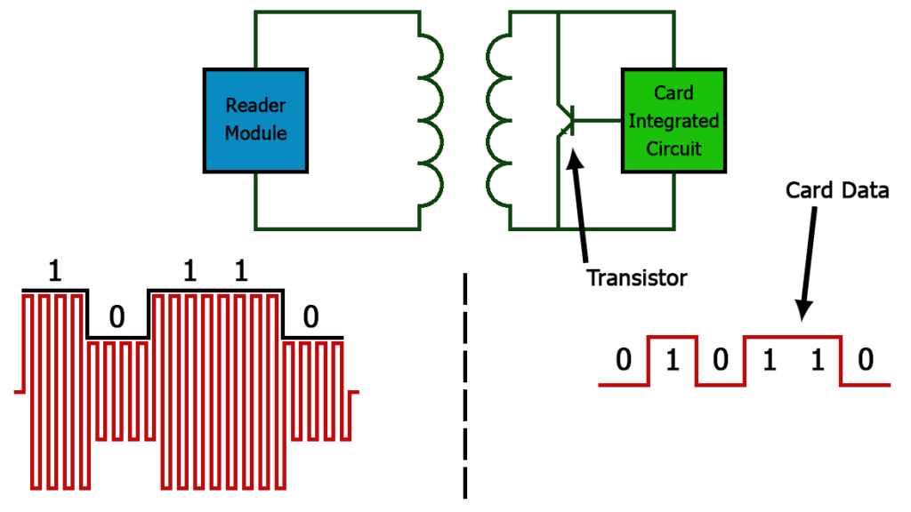
The RFID card integrated circuit turns the transistor on and off sequentially to the stored data. When the coil of the RFID Card is shorted the coil on the RFID Reader consumes more current, Thus the Module measures the energy consumption variation and then converts it into ones and zeros.
How To Use The RC522 RFID Module With Arduino
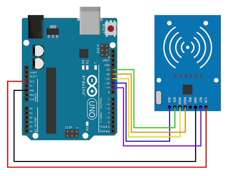
RC522 RFID And Arduino Schematic
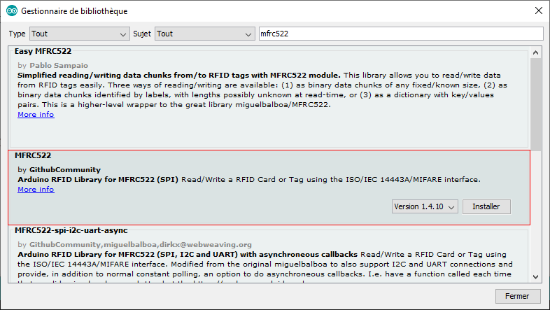
In the Arduino IDE, navigate to Sketch > Include Library > Manage Libraries, then write in the search bar mfrc522 then install the one by GithubComunity
Go to File > Examples > MFRC522 > DumpInfo
Upload the sketch and when you open the serial monitor you will see the card UID, the card SAK which is the manufacturer identifier and the type and the size of the memory, and a model for it composed of 16 sectors each sector is divided into 4 blocks and each block can store 16 bytes of data.
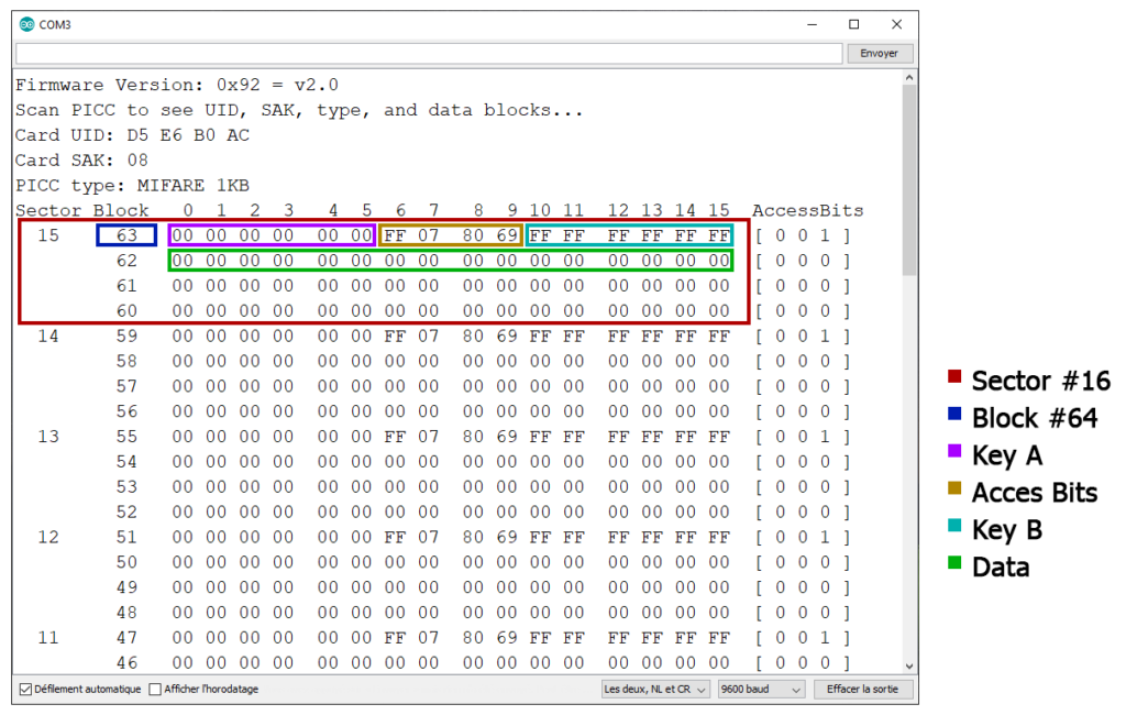
the 4th block of each sector is called Sector Trailer it contains two security keys called Key A and Key B and between them, there is 4 bit called Acces Bit.
if you do not know at least 1 of the two keys you will not be able to access the memory data or change or change anything on it.
RC522 RFID Module Simple Project With Arduino
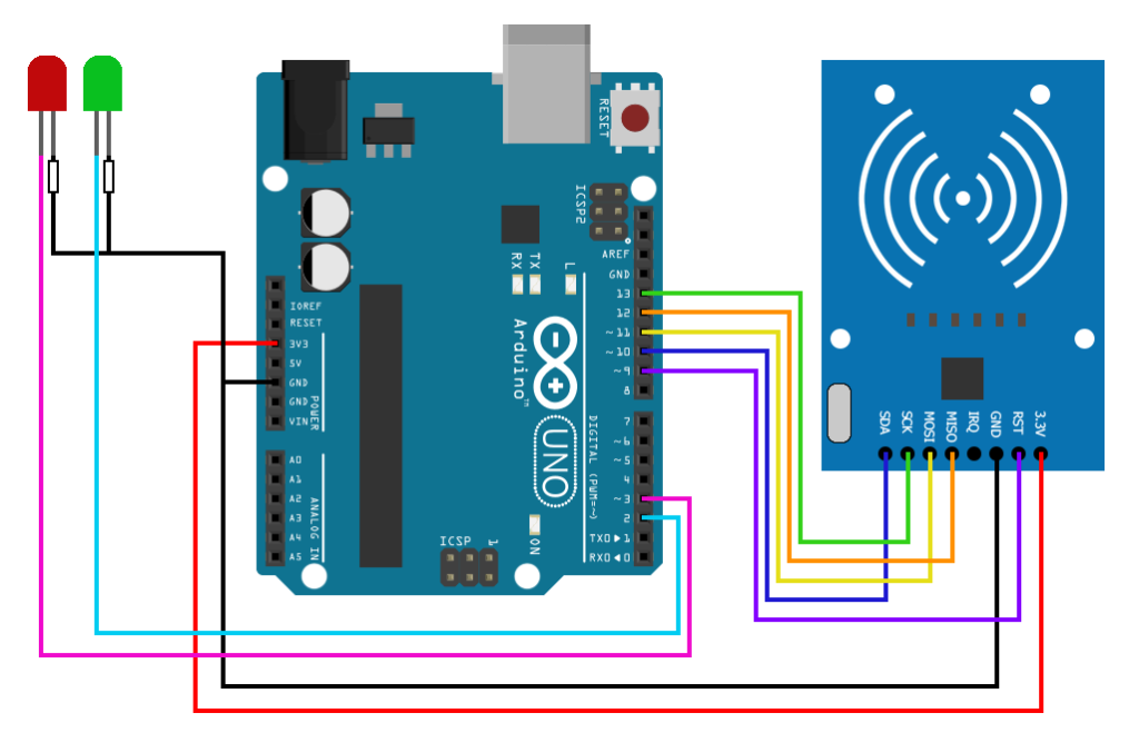
Schematic
Arduino Code
#include <SPI.h>
#include <MFRC522.h>
#define RST_PIN 9
#define SS_PIN 10
#define ledGreen 2
#define ledRed 3
MFRC522 mfrc522(SS_PIN, RST_PIN);
byte tagUID[4] = {0xD5, 0xE6, 0xB0, 0xAC};
void setup()
{
  Serial.begin(9600);
  SPI.begin();
  mfrc522.PCD_Init();
  pinMode(ledRed, OUTPUT);
  pinMode(ledGreen, OUTPUT);
}
void loop()
{
  if ( ! mfrc522.PICC_IsNewCardPresent()) {
  return false;
  }
  if ( ! mfrc522.PICC_ReadCardSerial()) {
  return false;
  }
  if (mfrc522.uid.uidByte[0] == tagUID[0] &&
      mfrc522.uid.uidByte[1] == tagUID[1] &&
      mfrc522.uid.uidByte[2] == tagUID[2] &&
      mfrc522.uid.uidByte[3] == tagUID[3] )
      {
        digitalWrite(ledGreen, HIGH);
        digitalWrite(ledRed, LOW);
        delay(1000);
      }
      else
      {
        digitalWrite(ledGreen, LOW);
        digitalWrite(ledRed, HIGH);
        delay(1000);
      }
  mfrc522.PICC_HaltA();
  digitalWrite(ledGreen, LOW);
  digitalWrite(ledRed, LOW);
}