How Does The 4×4 Keypad Works And How To Use It With Arduino

How Does The 4×4 Keypad Works

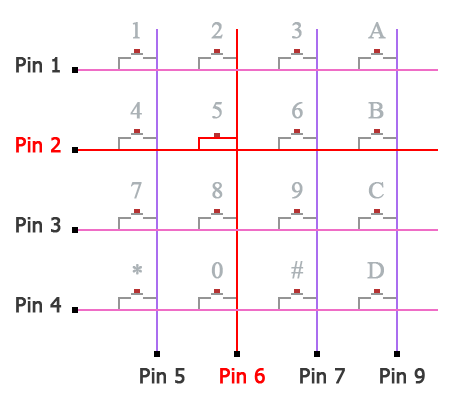
The 4×4 keypad is composed of 16 buttons connected in a certain way as shown in the next figure. Each end of a wire (4 horizontal pink wires and 4 vertical violet wires) will represent a pin.

For example, when button number 5 is pressed, Pin 2 and Pin 6 are connected and to know that using the Arduino we have to follow the following instruction.

  1. Set pins 1, 2, 3, and 4 to a HIGH level and pins 5, 6, 7, and 8 to a LOW level.
  2. Check which Pin from pins 1, 2, 3, and 4 went to a LOW level. The pin will go to a LOW level because in the microcontroller here, we used the internal pull-up resistor to set it to a HIGH level, and when we ground the pin it will no longer stay pulled up HIGH and it will go LOW.
  3. Memorize pin 2 because it went LOW.
  4. Set each pin sequencly from pins 5, 6, 7, and 8 to a HIGH level and check if pin 2 went back to a HIGH level. when pin 2 went back to LOW check which pin from pins 5, 6, 7, and 8 led pin 2 to be HIGH (in this case pin 6).
  5. Check which symbol, number, or letter corresponds to pin 2 and pin 6.


How To Use The 4x4 Keypad With Arduino

Unisng Mark Stanley And Alexander Brevig Library

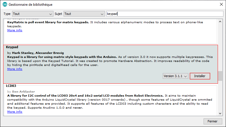
In the Arduino IDE, navigate to Sketch > Include Library > Manage Libraries, then write in the search bar keypad, then install the one by Mark Stanley and Alexander Brevig.
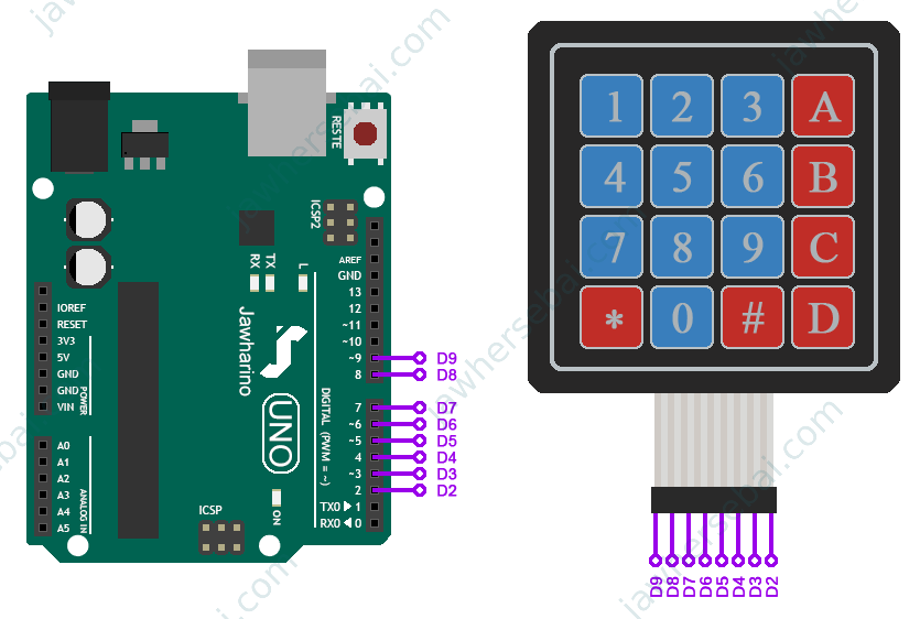
Schematic

Connect your keypad to the Arduino like it is shown in the next schematic. Open Arduino IDE and upload the code. In the end, you can see the results on the serial monitor once you press any button on the keypad.

Arduino Code

#include<Keypad.h>
const byte ROWS = 4;
const byte COLS = 4;
char keysTab[ROWS][COLS] = {
  {'1','2','3','A'},
  {'4','5','6','B'},
  {'7','8','9','C'},
  {'*','0','#','D'}
};
byte rowPins[ROWS] = {9, 8, 7, 6};
byte colPins[COLS] = {5, 4, 3, 2};
Keypad myKeypad = Keypad( makeKeymap(keysTab), rowPins, colPins, ROWS, COLS);
void setup(){
  Serial.begin(9600);
}
void loop(){
  char Key = myKeypad.getKey();
  if (Key){
    Serial.println(Key);
  }
}

Serial Monitor Results

How To Make A Door Lock System Using The 4x4 Keypad And Arduino

In this project, I will use the 4×4 keypad to enter a code composed of 4 digits
I will use the hashtag ‘#’ to confirm the code, And i will use the star ‘*’ to delete the code in case i made a mistake entering it.

I will be using a buzzer to make a sound on each time i press a button, And i will use a different length of sound on each time i press the hashtag or the star. also, I will make a different type of sound when i enter the wrong password.

Schematic

Arduino Code

#include<Servo.h>
#include<Keypad.h>
int key_counter;
bool one_buzz_variable = false;
int servo_position;
bool opening_variable = false;
bool opening_state = false;
unsigned long opening_previous_time;
const unsigned long opening_delay = 5000;
bool keys_stop = false;
bool red_led_blinking_stop = false;
bool red_led_state = false;
unsigned long red_led_previous_time;
const unsigned long red_led_delay = 1000;
bool last_key_pressed_time_stop = false;
unsigned long last_key_pressed_time;
const unsigned long error_delay = 6000;
int buzzer_short_delay_counter;
bool buzzer_short_delay_variable = false;
bool buzzer_short_delay_State = false;
unsigned long buzzer_short_delay_previous_time;
const unsigned long buzzer_short_delay = 100;
int buzzer_long_delay_counter;
bool buzzer_long_delay_variable = false;
bool buzzer_long_delay_State = false;
unsigned long buzzer_long_delay_previous_time;
const unsigned long buzzer_long_delay = 500;
const int buzzer_pin = 13;
const int red_led_pin = 10;
const int green_led_pin = 11;
const byte rows_number = 4; 
const byte columns_number = 4;
char keys_table[rows_number][columns_number] = {
{'1','2','3', 'A'},
{'4','5','6', 'B'},
{'7','8','9', 'C'},
{'*','0','#', 'D'}
};
byte rows_pins[rows_number] = {9, 8, 7, 6};
byte columns_Pins[columns_number] = {5, 4, 3, 2}; 
Servo myservo;
Keypad my_keypad = Keypad( makeKeymap(keys_table), rows_pins, columns_Pins, rows_number, columns_number);
const String master_password = "5079";
String input_password = "";
void setup() {
input_password.reserve(10); 
pinMode(buzzer_pin, OUTPUT);
pinMode(red_led_pin, OUTPUT);
pinMode(green_led_pin, OUTPUT); 
myservo.attach(12); 
myservo.write(0);
}
void red_led_blinking_function()
{
if(millis() - red_led_previous_time >= red_led_delay)
{
red_led_previous_time = millis();
if(red_led_state == false)
red_led_state = true;
else
red_led_state = false; 
digitalWrite(red_led_pin, red_led_state);
}
}
void buzzer_short_delay_function()
{
if(millis() - buzzer_short_delay_previous_time >= buzzer_short_delay)
{
buzzer_short_delay_previous_time = millis();
buzzer_short_delay_counter++;
if(buzzer_short_delay_State == false)
{
buzzer_short_delay_State = true;
} 
else
{
buzzer_short_delay_State = false; 
} 
digitalWrite(buzzer_pin, buzzer_short_delay_State);
}
}
void buzzer_long_delay_function()
{
if(millis() - buzzer_long_delay_previous_time >= buzzer_long_delay)
{
buzzer_long_delay_previous_time = millis();
buzzer_long_delay_counter++;
if(buzzer_long_delay_State == false)
{
buzzer_long_delay_State = true;
} 
else
{
buzzer_long_delay_State = false; 
} 
digitalWrite(buzzer_pin, buzzer_long_delay_State);
}
}
void opening_function()
{
if(millis() - opening_previous_time >= opening_delay)
{
opening_previous_time = millis();
if(opening_state == false)
{
opening_state = true;
servo_position = 90;
red_led_blinking_stop = true;
digitalWrite(red_led_pin, false);
keys_stop = true;
} 
else
{ 
opening_previous_time = (millis() - opening_delay);
servo_position = 0;
opening_state = false; 
red_led_blinking_stop = false;
keys_stop = false;
opening_variable = false; 
} 
digitalWrite(green_led_pin, opening_state);
myservo.write(servo_position);
}
}
void loop() {
char key = my_keypad.getKey();
if(last_key_pressed_time_stop == false)
{
last_key_pressed_time = millis();
} 
if(red_led_blinking_stop == false)
{
red_led_blinking_function();
}
if(opening_variable == true)
{
opening_function();
}
if(buzzer_short_delay_variable == true)
{
buzzer_short_delay_function();
if(buzzer_short_delay_counter == 6)
{
buzzer_short_delay_counter = 0;
buzzer_short_delay_variable = false;
}
}
if(buzzer_long_delay_variable == true)
{
buzzer_long_delay_function();
if(buzzer_long_delay_counter == 2)
{
buzzer_long_delay_counter = 0;
buzzer_long_delay_variable = false;
}
} 
if(one_buzz_variable == true)
{
buzzer_short_delay_function();
if(buzzer_short_delay_counter == 2)
{
buzzer_short_delay_counter = 0;
one_buzz_variable = false;
}
}
if(keys_stop == false)
{ 
if (key)
{
last_key_pressed_time = millis();
last_key_pressed_time_stop = true;
if(key == '*')
{
last_key_pressed_time_stop = false;
key_counter = 0;
buzzer_long_delay_variable = true;
input_password = "";
}
else if (key == '#')
{
last_key_pressed_time_stop = false;
key_counter = 0;
if(input_password == master_password)
{
opening_variable = true;
buzzer_long_delay_variable = true;
}
else
{
buzzer_short_delay_variable = true;
}
input_password = "";
}
else
{
input_password += key;
key_counter++;
if(key_counter < 9)
one_buzz_variable = true;
}
}
} 
if(key_counter == 9)
{
buzzer_short_delay_variable = true;
last_key_pressed_time_stop = false;
key_counter = 0;
input_password = "";
} 
if(millis() - last_key_pressed_time >= error_delay)
{
buzzer_short_delay_variable = true;
last_key_pressed_time_stop = false;
key_counter = 0;
input_password = "";
}
}						

Arduino Code Explantation

This following video is an explanation of the arduino based door lock system code.

If you did not understand something from the explanatory video of the code, write your question in the comment section below and i will try to explain it in more detail.

Leave a Reply

Your email address will not be published. Required fields are marked *

Scroll to Top