How to Make a Door Lock System with Arduino + Code Explanation
Hi, I’m Jawher!
In this article, I’ll guide you through the process of building a simple and effective Arduino-based door lock system, perfect for adding a layer of security to your home or workspace.

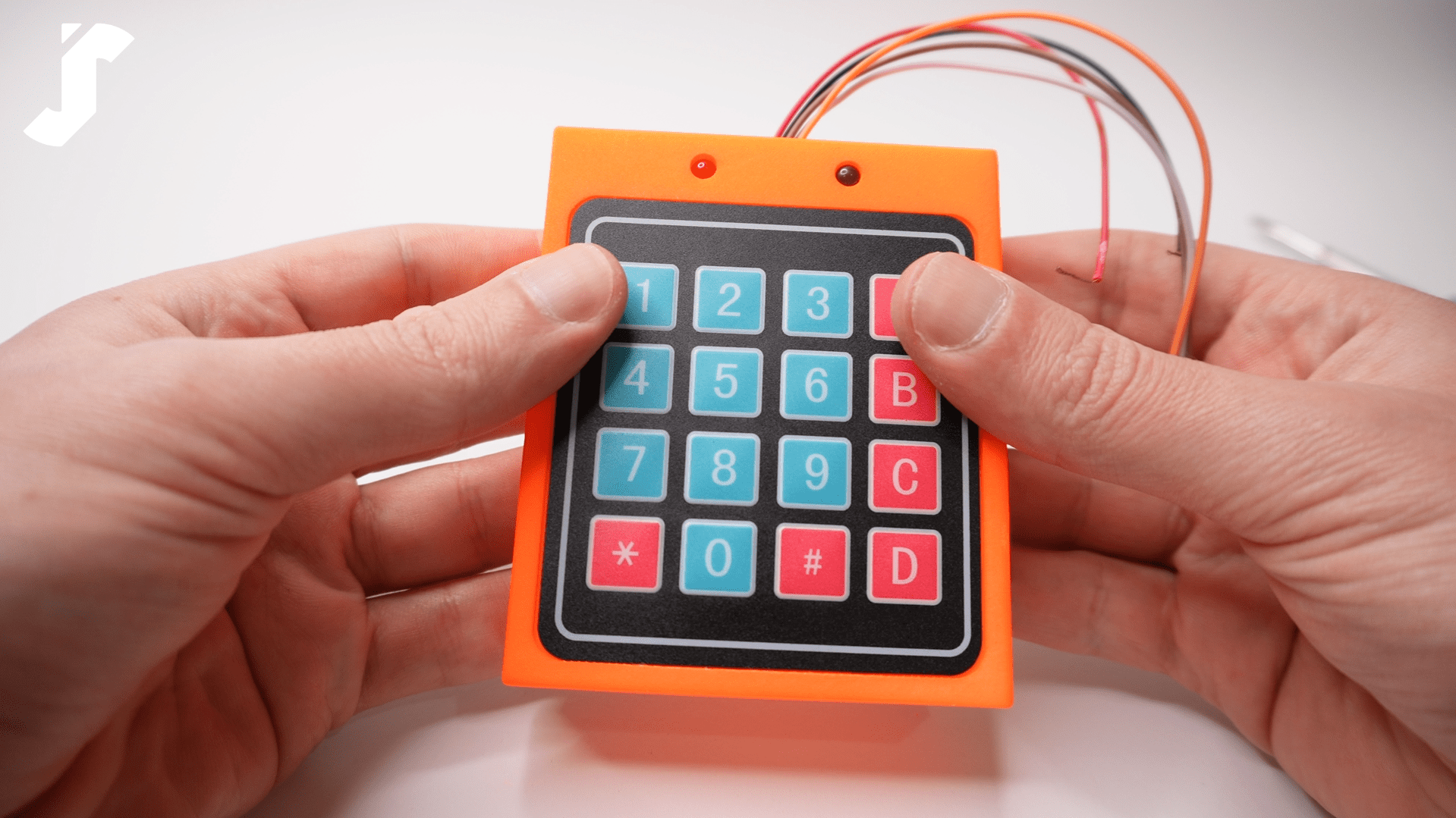
The device controls an SG90 servo motor to rotate its output shaft by 90° to simulate the unlocking action, alongside a 4×4 keypad for password input.
To enhance user interaction, the system includes a red LED that blinks every second to indicate standby mode, a green LED that lights up when access is granted, and a buzzer that provides audible feedback during each step of the process.
System Operation Overview
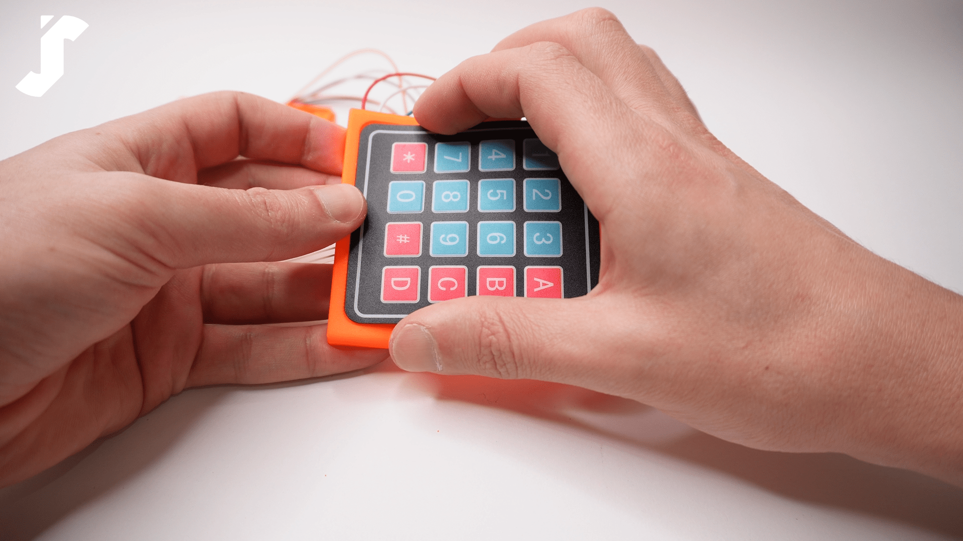
When the system is idle, a red LED blinks every second. To gain access, the user must enter a 4-digit password using the keypad and press the “#” key to confirm. If a mistake is made, the “*” key allows the user to delete and re-enter the password. Each keypress is accompanied by a buzzer sound for feedback.
Upon entering the correct password, the SG90 servo motor rotates its shaft by 90°, the red LED stops blinking, and the green LED turns on. Simultaneously, the buzzer generates a distinct confirmation tone to indicate successful access.
After 5 seconds, the system automatically relocks: the servo motor returns to its initial position, the green LED turns off, and the red LED resumes blinking.
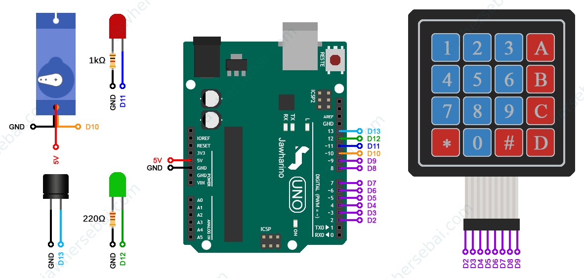
Wiring & Circuit Setup
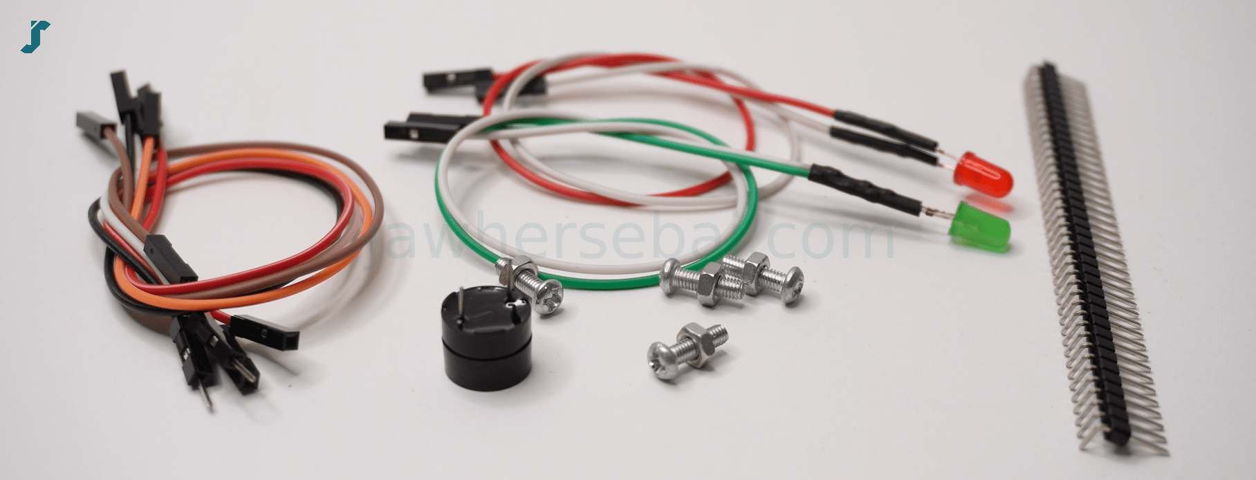
Here are the essential components required for the system:
- Arduino UNO
- SG90 Servo Motor
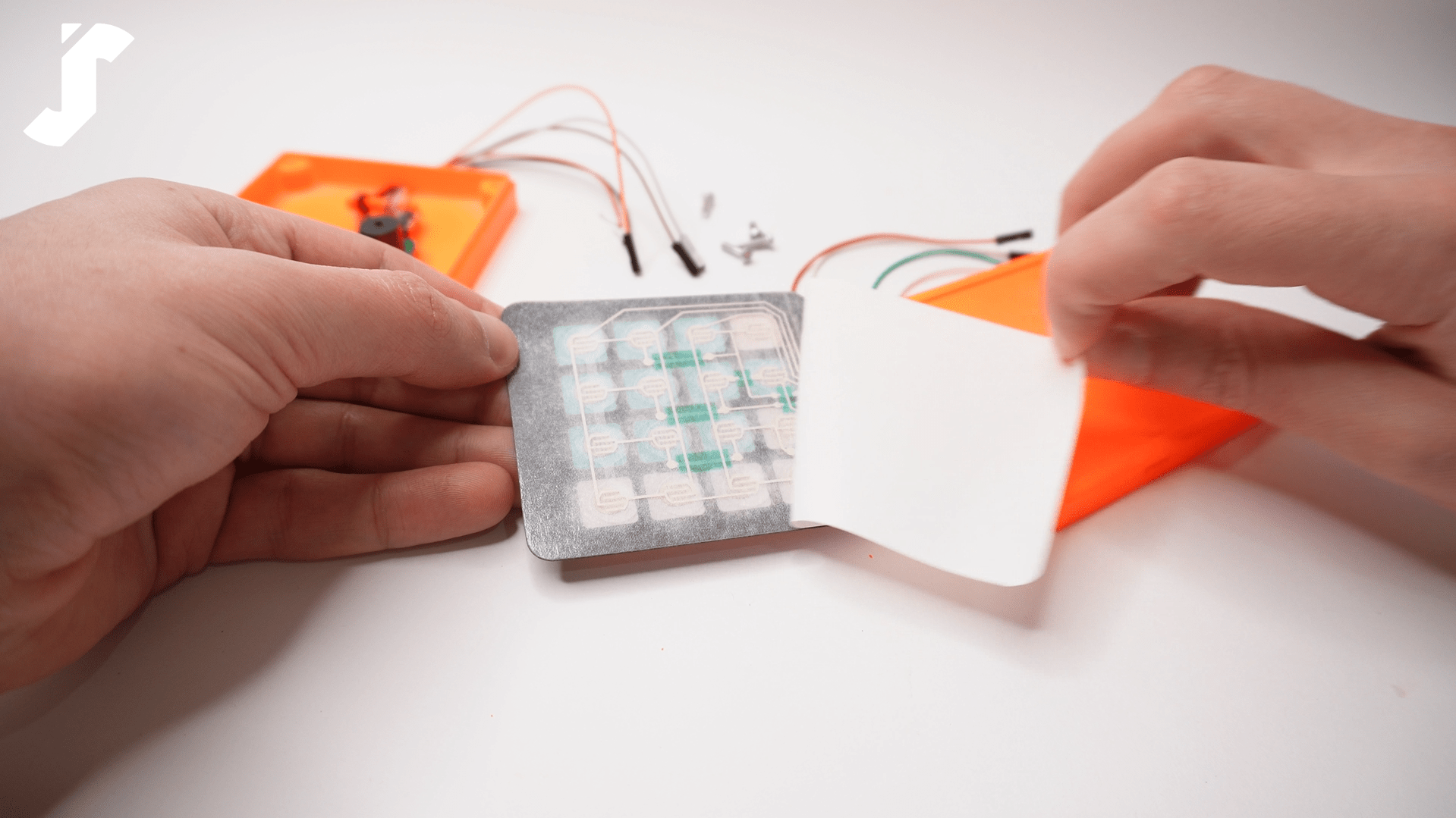
- 4×4 Keypad
- 5V Active Buzzer
- 5mm Green LED
- 5mm Red LED
- 1 kΩ Resistor
- 220 kΩ Resistor
- Jumper Wires (variety of male-to-male and female-to-male)
Check out how I made the connections between these components below using my Home-made Arduino UNO.
The Arduino Sketch
I defined a set of specifications based on what I imagined the system would do in operation to provide myself with clear instructions for writing the sketch. For example, if the user enters a password but fails to press the “#” key within 10 seconds, the system will automatically delete the entered password and trigger an error sound. In addition, I chose to use the millis() function to perform more than one task simultaneously, rather than the delay() function, which freezes the code for a certain determined period before executing anything else.
Watch my full explanation video below to see how the code is built step by step, and I encourage you to rewrite it yourself to enhance your coding skills.
If you’d like to save time and download the working code instantly, it’s available for just $1.
By purchasing the download, you’re not just getting the code—you’re also supporting my work and helping me keep creating and sharing more DIY tech projects.
The PCB
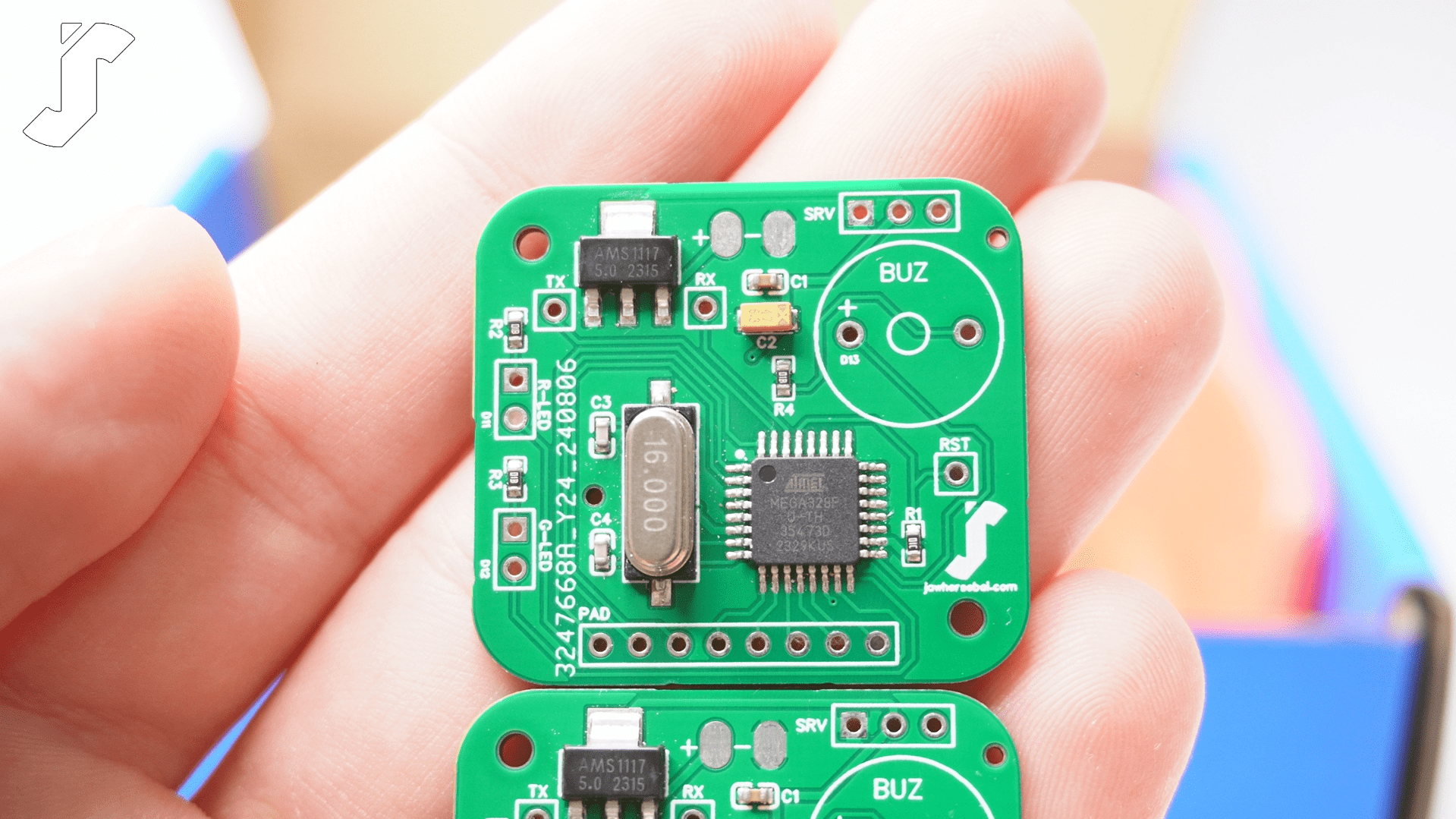
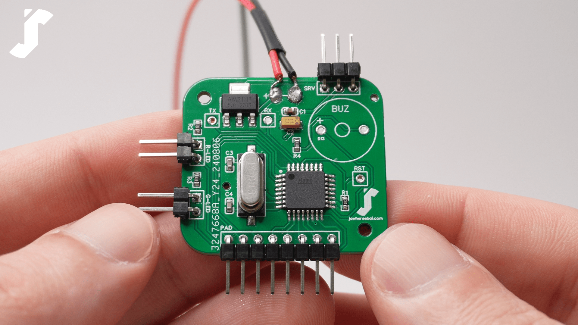
I used the online design tool EasyEDA to create a PCB for my project, selecting the ATMEGA328P-AU chip to save space, rather than using the larger ATMEGA328P-PU.
By designing my own PCB, I was able to include only the essential components of the Arduino UNO board, resulting in a cleaner, more professional setup without unnecessary bulk.
Feel free to Open In Editor the schematic diagram and PCB layout and Download the Gerber, BOM, and CPL files.

After preparing my PCB, I visited jlcpcb.com and selected Instant Quote. I then uploaded the GERBER file, opted for green as the PCB color, selected LeadFree HASL for the surface finish, activated the PCB assembly service, and uploaded both the BOM and CPL files.
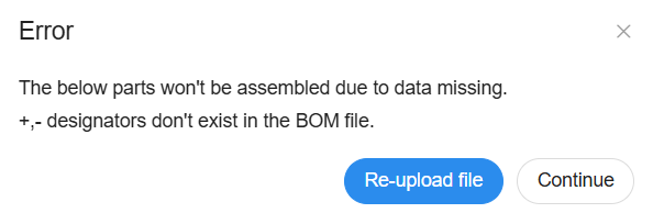
As for the ‘+’ and ‘-‘, they are not components but merely conductive copper areas on the PCB. So, when you get an error, click on continue.
I prefer not to have certain items pre-assembled by JLCPCB and chose to solder them myself upon receiving the PCB. These items are designated as BUZ, G-LED, R-LED, RST, RX, TX, PAD, and SRV.
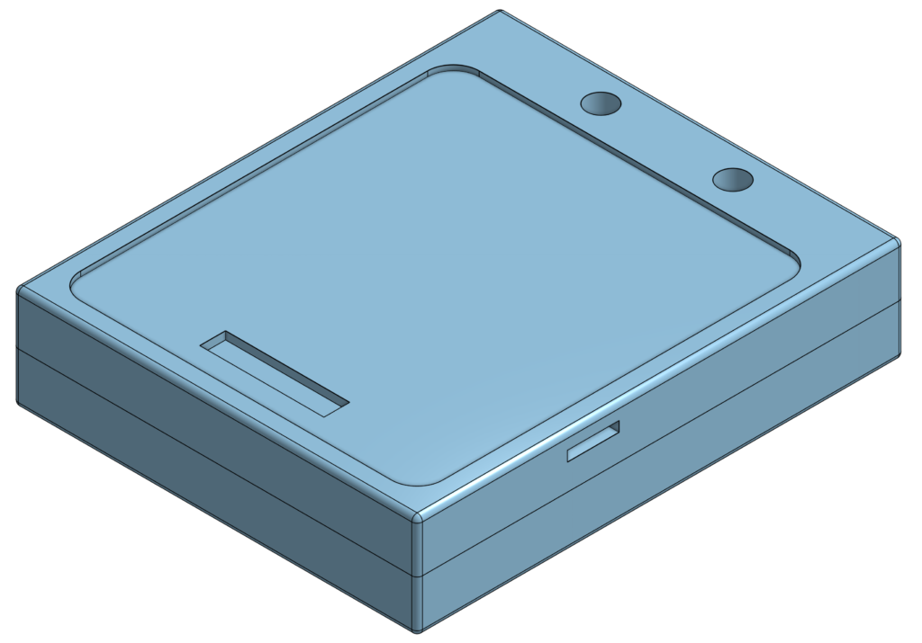
The Enclosure Box
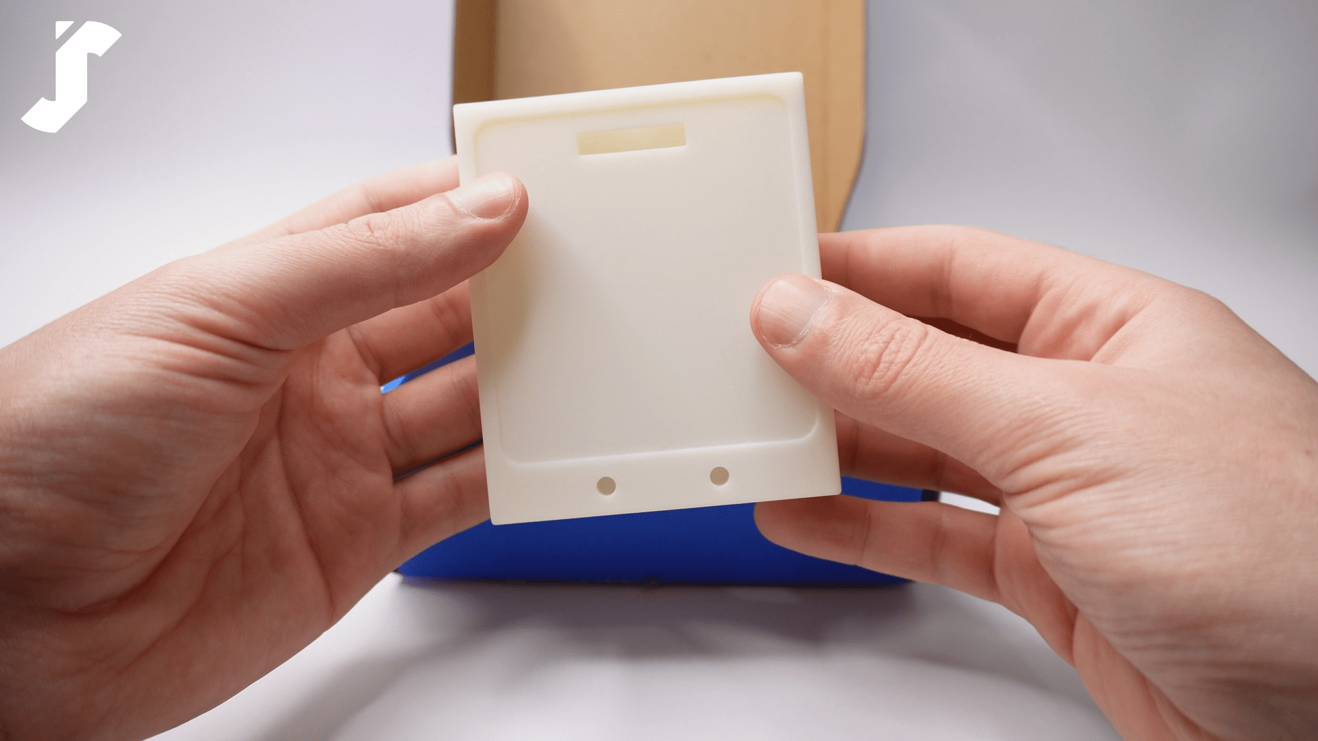
To complete the project, I want to make an enclosure box for the PCB in a special form to give the system a final look as a door lock device. Therefore, to design the model, I used an online CAD software called Onshape.
JLCPCB also provides a 3D printing service, so I uploaded my STL files as well and submit my order. I chose the SLA (Resin) 3D technology and CBY Resin material.
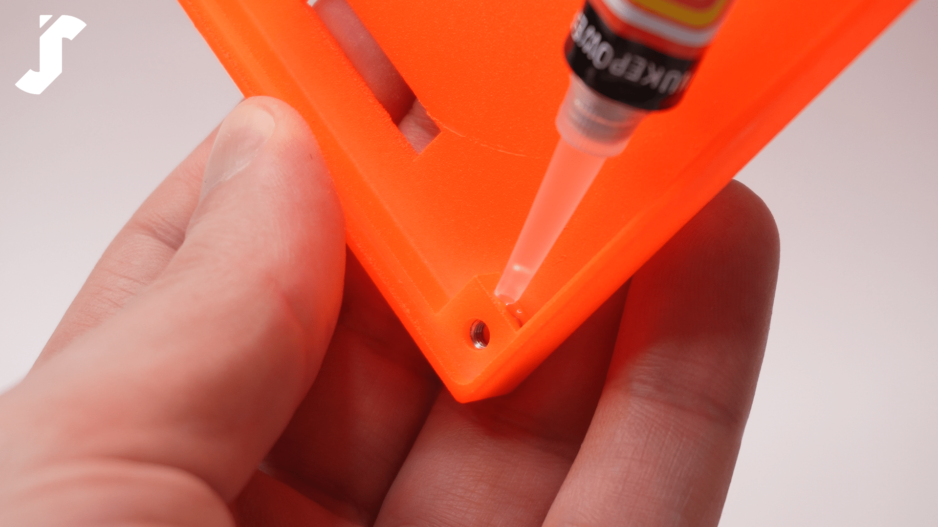
Before ordering my 3D model online, I tried a local 3D printing service, but the result was not satisfying, as I faced issues with fitting the nut into the designed pocket and the LED into the intended hole.

This is why, as soon as I received my package from JLCPCB, I immediately verified the dimensions, which were perfect, as well as the PCB and PCBA.

Uploading the Sketch
You can use a USB to TTL serial converter to upload the sketch to the ATMEGA328P-AU chip. However, I prefer to use an Arduino UNO as ISP (in-system programmer) for sketch upload.
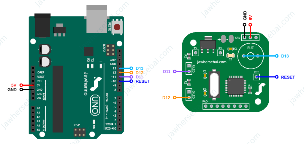
Once the boards are connected as shown above, follow these steps:
- Connect the Arduino UNO to the computer and open Arduino IDE.
- In Tools select the board Arduino Uno and the port the board is connecting to.
- Open File > Examples > 11.ArduinoISP > ArduinoISP then upload the sketch.
- Once uploaded, go to Tools again and select the board Arduino Nano, the processor ATmega328P, the port the Arduino UNO is connecting to, then change the programmer from AVRISP mkII to Arduino as ISP, and finally click Burn Bootloader.
- Open the desired sketch to upload, and from the menu bar open sketch, then click on Upload Using Programmer.
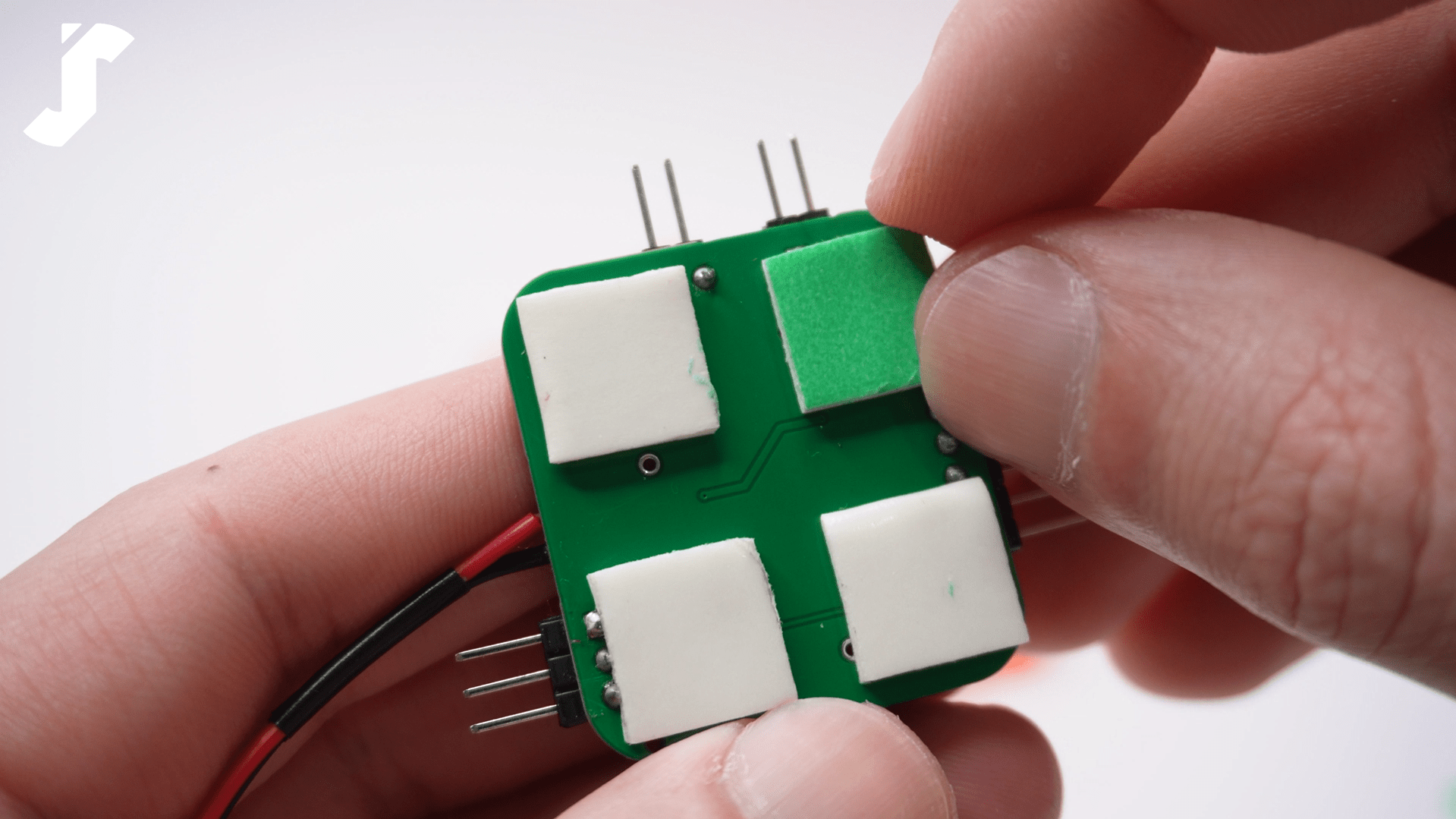
Assembling All the Parts
Before I started putting everything together, I wired the LEDs and prepared my items. These included a 90-degree male pin header (2.5mm), four Phillips head screws (M3×10mm), and four M3 hexagon nuts.
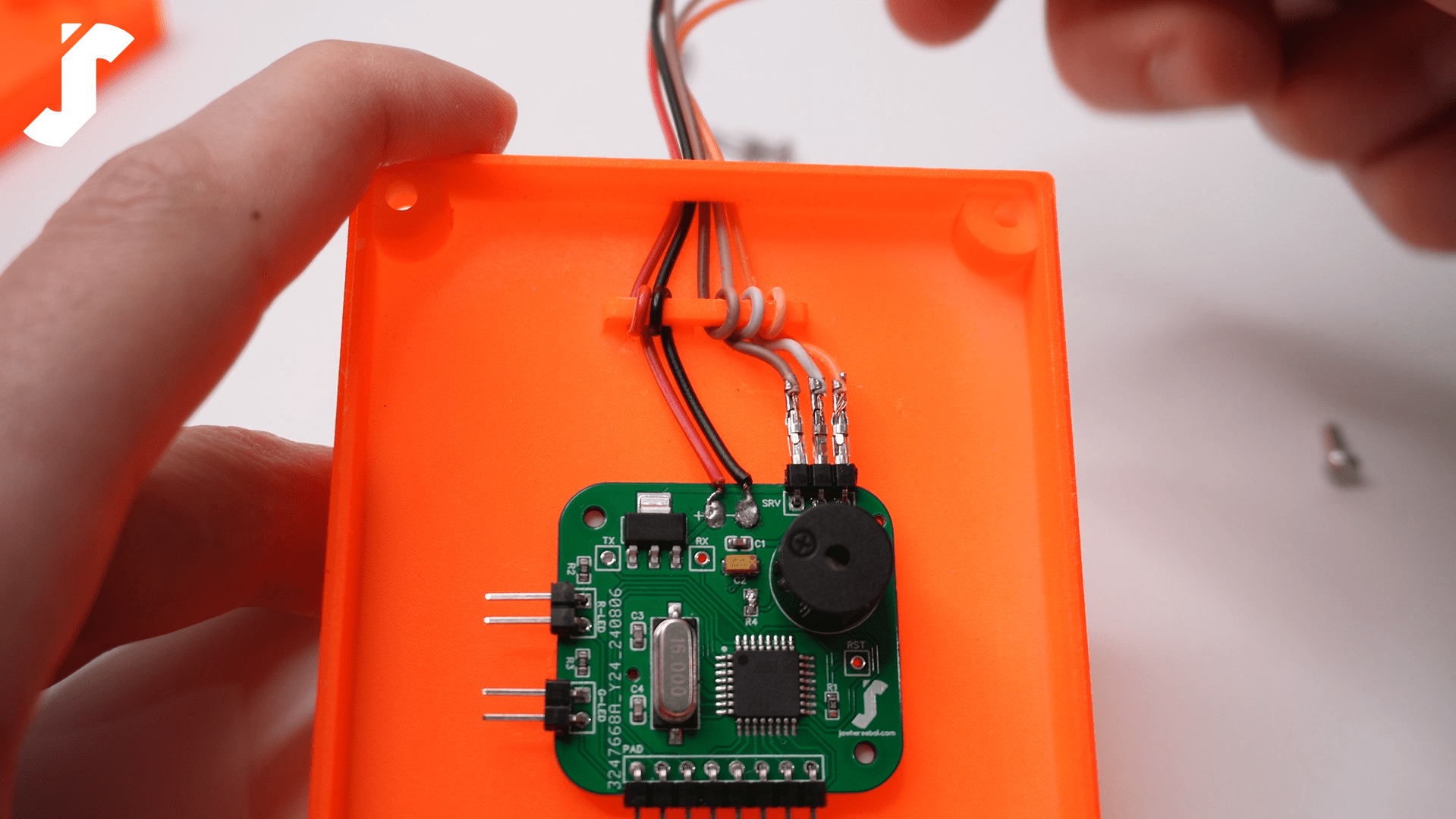
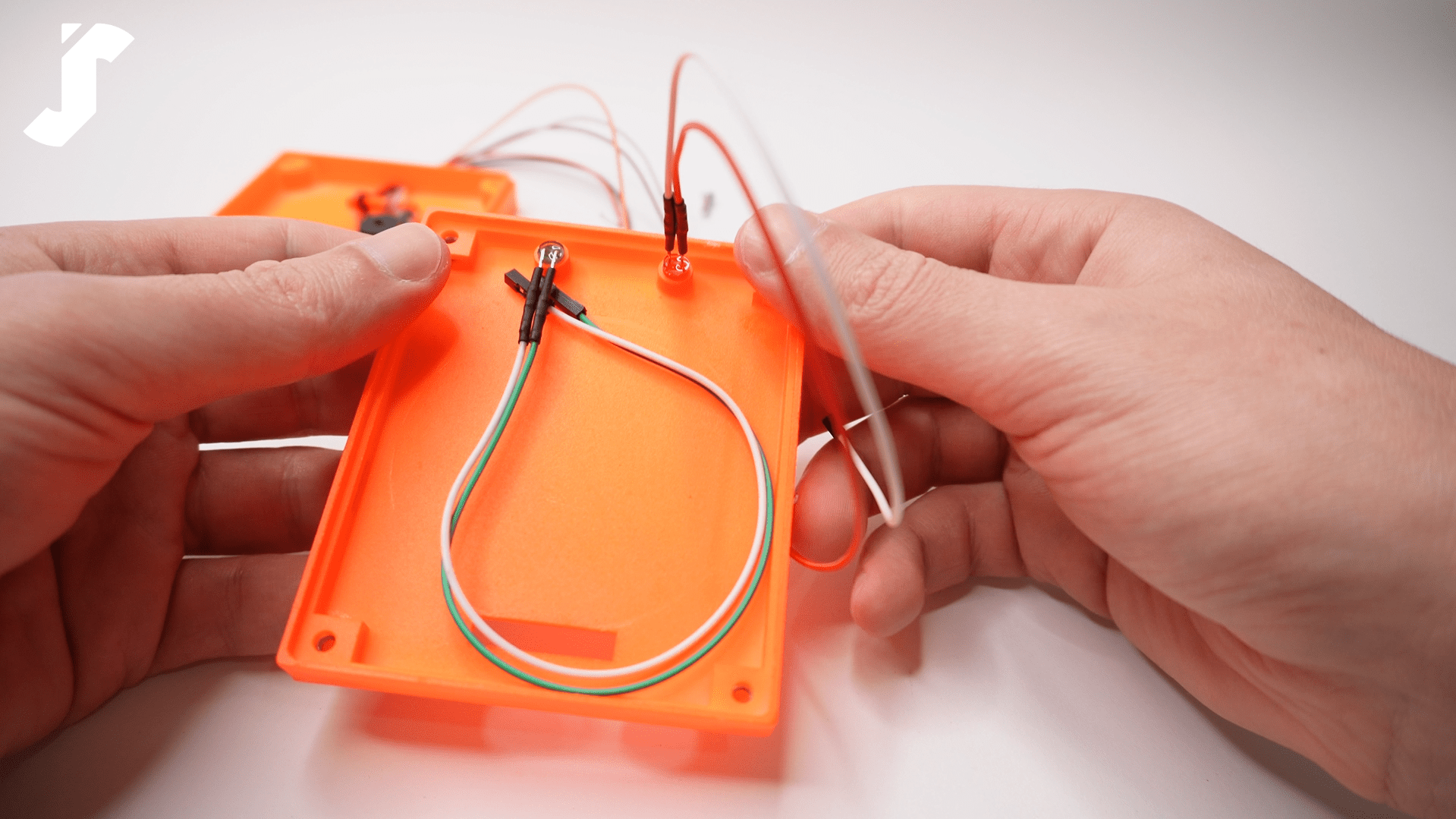
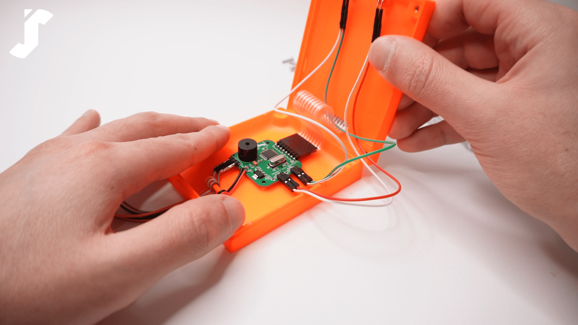
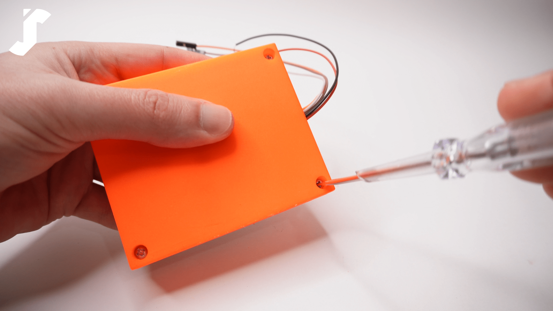
The step that involves securing the power and servo wires beneath the bridge constructed within the enclosure box requires some time and patience. It made me think of changing the PCB footprint and the 3D part design in the future if I want to make version two. But for now, the satisfaction of seeing my hard work come together is incredibly rewarding.
The Video
Watch below the video tutorial for this project—If you find it helpful, consider subscribing to my YouTube channel for more exciting tech projects and tutorials. Your support helps me create more content, and I’d love to have you along for the journey!
I hope this tutorial gave you a clear understanding of how the door lock system works! If you have any questions or ideas for improvements, feel free to share them. Stay tuned for more exciting projects, and thanks for stopping by!