
Motorized Positioning Platform for Automated EIT Dataset Collection
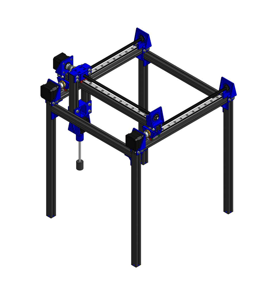
Hello and welcome! I’m excited to share one of the most meaningful projects I worked on during my Embedded Systems Project Lab at TU Chemnitz. Together with my colleagues, we built a Motorized Positioning Platform for Automated EIT Dataset Collection, a full hardware‑software system designed to make Electrical Impedance Tomography experiments faster, more precise, and completely automated.
What is Electrical Impedance Tomography (EIT)?
Electrical Impedance Tomography (EIT) is a non‑invasive imaging technique that tries to “see inside” an object using only electrical measurements taken on its surface. Instead of using X‑rays or ultrasound, EIT injects tiny electrical currents through electrodes placed around a tank or a body and then measures the resulting voltages.
From these voltages, a computer reconstructs a conductivity map, which is an image showing where the object is located inside the tank.
In simple words, EIT lets you track how an object changes the electrical field inside water, and from that, you can estimate its position or shape.

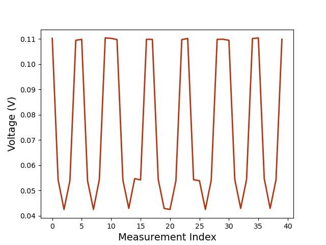
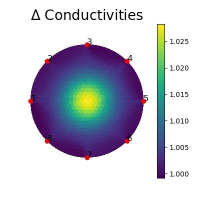
This technique is powerful, but it has one big challenge: the object must be moved to known positions with high accuracy so the reconstructed images can be validated [1]. Traditionally, this positioning is done manually, slowly, and inconsistently, which is prone to human error [2].
System Design
Our system was built to move an object precisely inside an EIT tank, along two linear axes (X and Y) and one rotational axis (Z) [3]. The goal was to automate the entire positioning process so that every measurement could be repeated exactly.
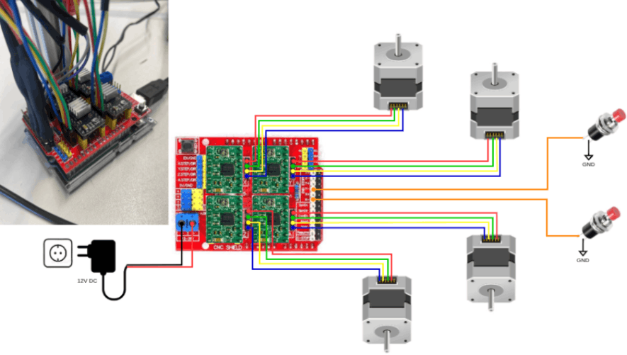
At the heart of the setup is an Arduino Uno connected to a CNC shield that drives four stepper motors through dedicated drivers. Two motors handle the X‑axis movement, one controls the Y‑axis, and another rotates the object. A desktop interface communicates with the Arduino via serial connection (UART), sending commands and receiving live position feedback.
This design allows the user to define the tank geometry, plan a sequence of positions, and start the automated routine with just a few clicks. Every position is tracked and logged in real time, ensuring traceable, reproducible data collection for EIT experiments.
Mechanical Architecture
The mechanical structure was designed to provide smooth, precise movement and enough workspace for different EIT tank sizes. The frame is built from lightweight aluminum extrusions, which are both rigid and easy to assemble.
Motion along the X and Y axes is achieved using lead screws and traveling nuts, converting the rotary motion of the stepper motors into linear translation. Each axis is guided by MGN12H linear rails, ensuring stability and accuracy during movement.
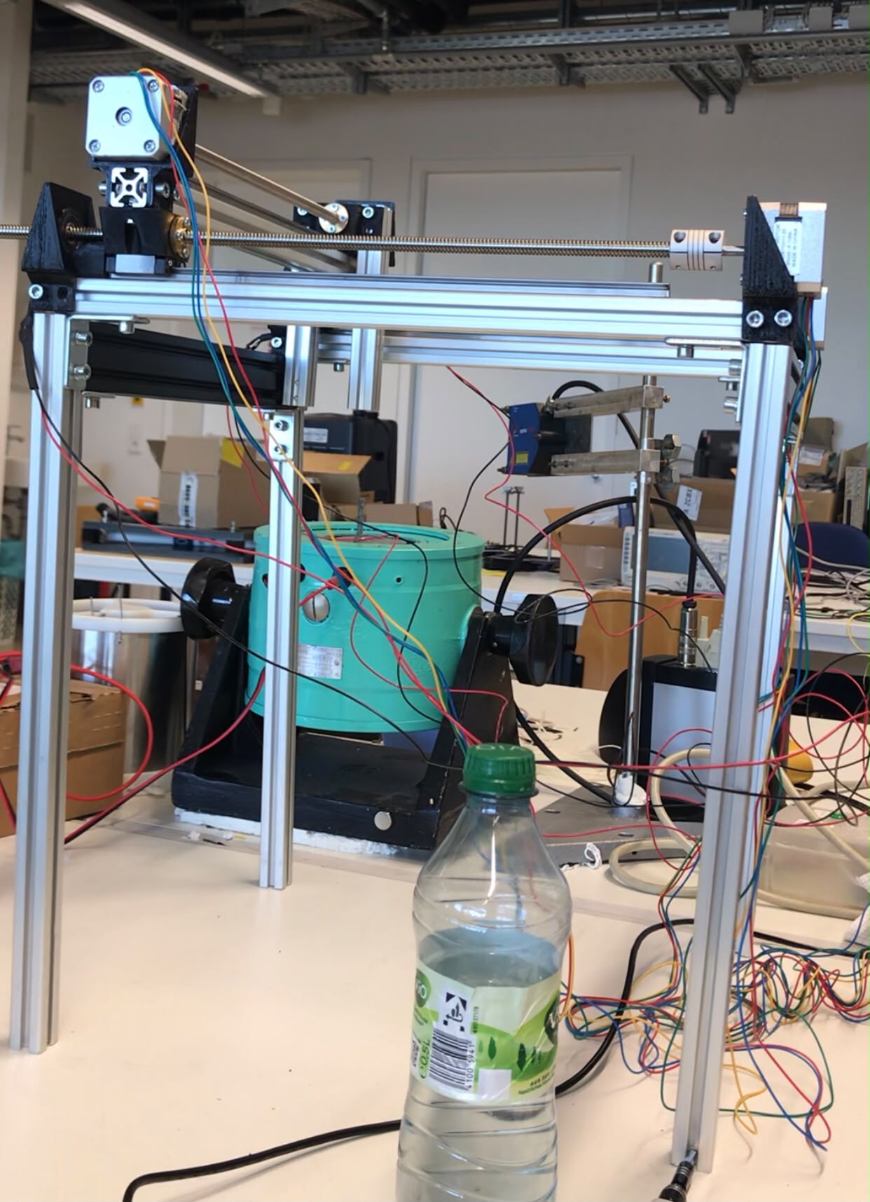
To keep the setup organized, we designed and 3D‑printed custom parts for motor mounts, bearing holders, and junction platforms. These printed components made the assembly compact and modular, facilitating future modifications or upgrades.
NEMA 17 Mount For 20x20mm Aluminum Profile
3D Housing for Bearing 8 x 22 x 7 mm
Linear Guide Carriage Mount – Type 1
Linear Guide Carriage Mount – Type 2
NEMA 17 Stepper Motor Mount for Z-Axis
Limit Switch Case
Corner Bracket 3D Model for 20x20mm Aluminum Profile
Electrical & Power Systems
The electronic system is the brain of our platform. It’s built around an Arduino Uno paired with a CNC shield, which controls up to four A4988 stepper drivers [4]. Each driver powers one motor, two for the X‑axis, one for the Y‑axis, and one for rotation.
To keep the system safe and precise, we added mechanical limit switches at both ends of every axis. These switches prevent over‑travel and help the platform automatically find its home position before starting any measurement.
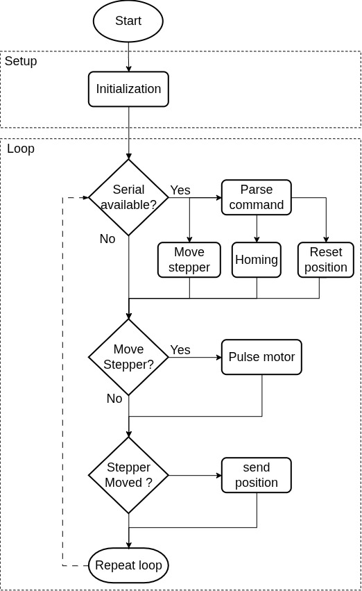
The firmware running on the Arduino continuously listens for commands from the desktop interface. It parses each instruction, moves the motors accordingly, and sends back live position data. The flowchart below shows the logic: initialization, command parsing, motion control, and position feedback, all running in a smooth loop.
Control & Interface
To make the system easy to use, we developed a desktop interface that acts as the command center for the entire platform. Built in Python using Tkinter and pySerial, it communicates with the Arduino through a simple serial connection.
The interface lets the user move the object inside the EIT tank, monitor its live position, and record every measurement point automatically. It includes a remote control panel for manual movement, a map view showing the tank and object path, and tabs for geometry setup, homing, and dataset export.
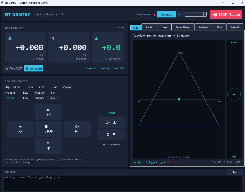
At the end of a run, all positions are saved and exported as a CSV file, perfectly synchronized with the EIT measurements. This makes the system not only automated but also traceable and reproducible, ready for data analysis or AI model training.
Results & Testing
After assembling the full system, we tested it across different tank shapes and object geometries. The platform performed reliably throughout testing: the homing routine consistently established a repeatable zero reference, the motors moved smoothly, the live map aligned perfectly with the real object’s position, and the automated sequences ran seamlessly without requiring any manual intervention.
During each test, the system exported a clean CSV dataset containing the exact X/Y/Z coordinates and timestamps. These labelled datasets can be directly used for EIT reconstruction, analysis, or even training AI models.
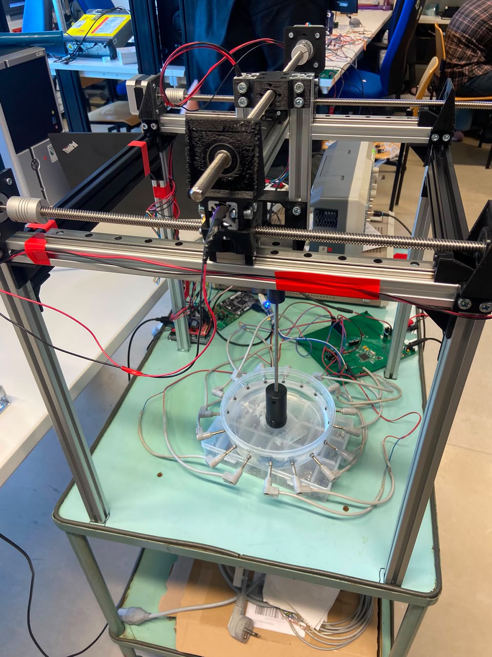
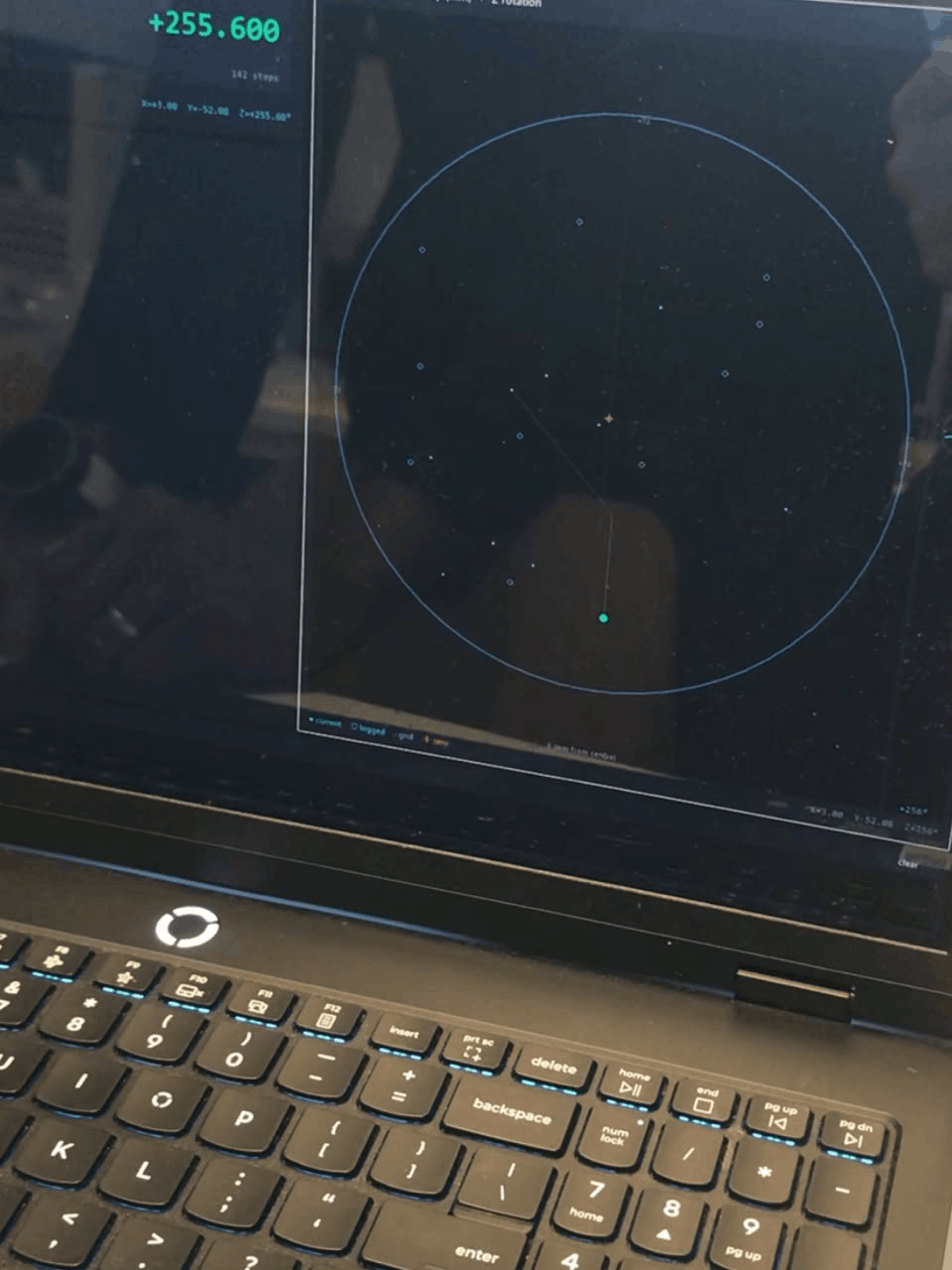
Building this project taught me how mechanical design, electronics, firmware, and software all connect to form one complete system. It was a challenging but very rewarding experience — especially seeing the platform move automatically and generate reproducible datasets for real EIT experiments.
Working with my colleagues, we created a low‑cost, open‑source solution that makes EIT data collection faster, more accurate, and fully automated. I’m proud to share it here, and I hope it inspires other students who want to build practical embedded systems.
Acknowledgements
This project would not have been possible without the guidance and support of our supervisors at the Chair of Measurement and Sensor Technology. A special thank you to Dr. Mariem Hafsa and Dipl.-Ing. Mejda Bouchhima for their continuous feedback, technical insights, and encouragement throughout the entire development process. Their expertise helped us refine our ideas, solve complex challenges, and successfully bring this automated EIT positioning platform to life.
References
[1] Maimaitijiang, Y., Böhm, S., Jaber, O., & Adler, A. (2010, April). A phantom based system to evaluate EIT performance. In Int. Conf. Electrical Bio-Impedance & Electrical Impedance Tomography Gainville, Fl, USA (pp. 4-8).
[2] Gaggero, P. O., Adler, A., Waldmann, A. D., Mamatjan, Y., Justiz, J., & Koch, V. M. (2015). Automated robust test framework for electrical impedance tomography. Physiological measurement, 36(6), 1227-1244.
[3] Chen, C. Y., Wu, Y. C., Huang, C. W., & Hsueh, P. W. (2011, November). The introduction of precision positioning and compensation technology in gantry-type platform. In 2011 First International Conference on Robot, Vision and Signal Processing (pp. 94-97). IEEE.
[4] Allegro MicroSystems, “A4988 DMOS Microstepping Driver with Translator and Overcurrent Protection,” Datasheet, Allegro MicroSystems LLC, Worcester, MA, USA, 2011.