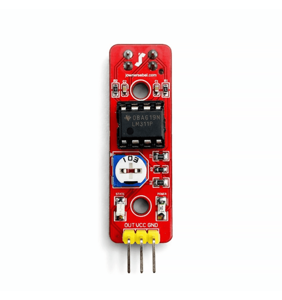
Hello and welcome to this video! Today, I will show you how I made an Infrared proximity sensor.
Since I was attracted to robotics clubs and the world of Arduino and sensors, I became eager to learn how to create such devices to gain more knowledge about electronics and PCB fabrication. I began by replicating the well-known Arduino UNO board, and now I am working on the TCRT5000 IR sensor.
NoteComponent footprints were adjusted based on what was available at my local electronics shop.
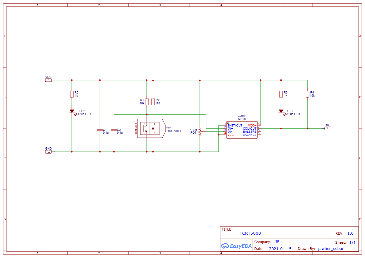
Circuit Schematic and GERBER File
I designed the schematic and PCB layout using EasyEDA and ordered the fabricated boards through JLCPCB. Please feel free to download the Gerber files provided below.
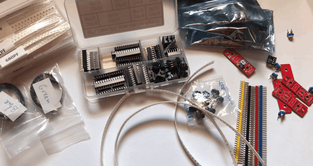
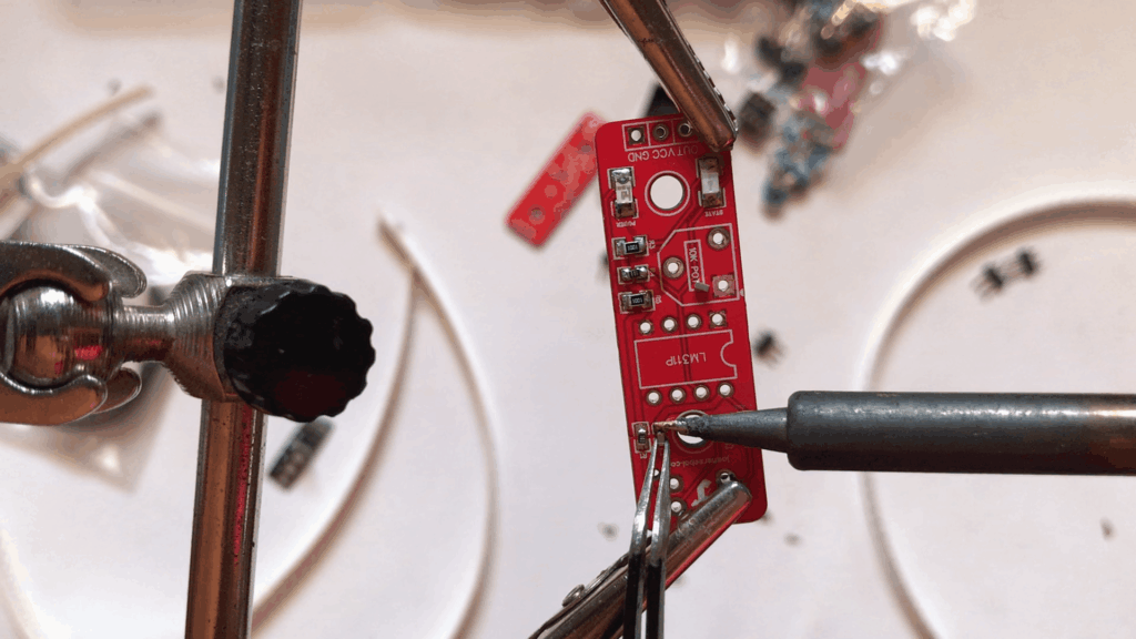
Once all the components and the fabricated PCB arrived, I moved on to my favorite part of the whole project: soldering. Sitting down at the bench, placing each surface-mount component, and watching the bare PCB transform into a functional circuit board is always the most satisfying step for me!
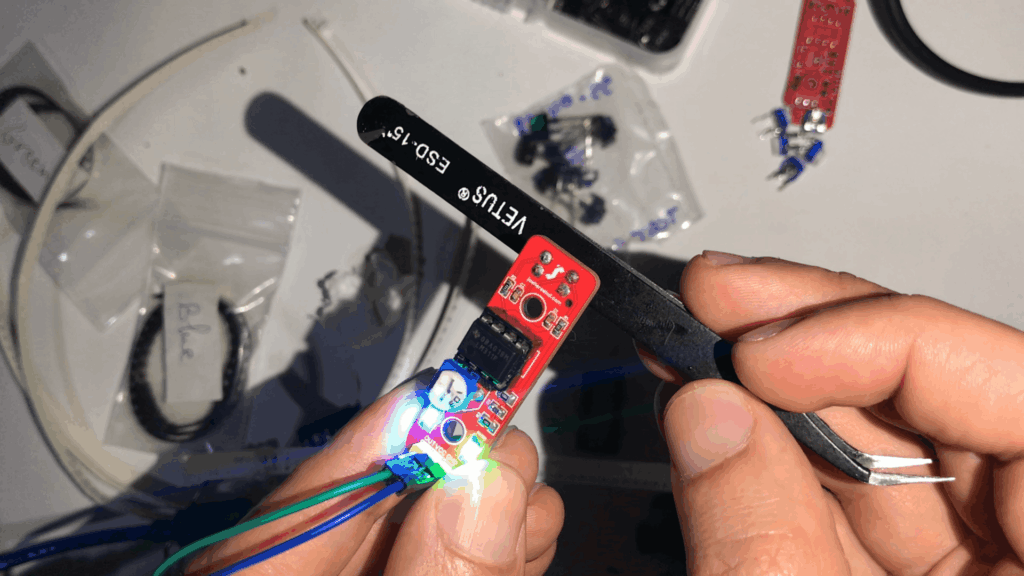
Once the soldering was complete, it was time to test it out. Since I didn’t have a standalone power supply or a voltage regulator on hand, I simply powered the sensor using the Arduino’s 5V and GND pins. After a quick tweak of the potentiometer to calibrate the sensitivity, the sensor worked perfectly!
All right! I hope you liked the design! If you have any questions, drop them down below in the comments section!